9
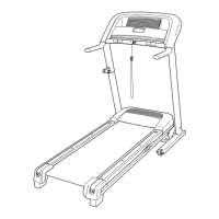
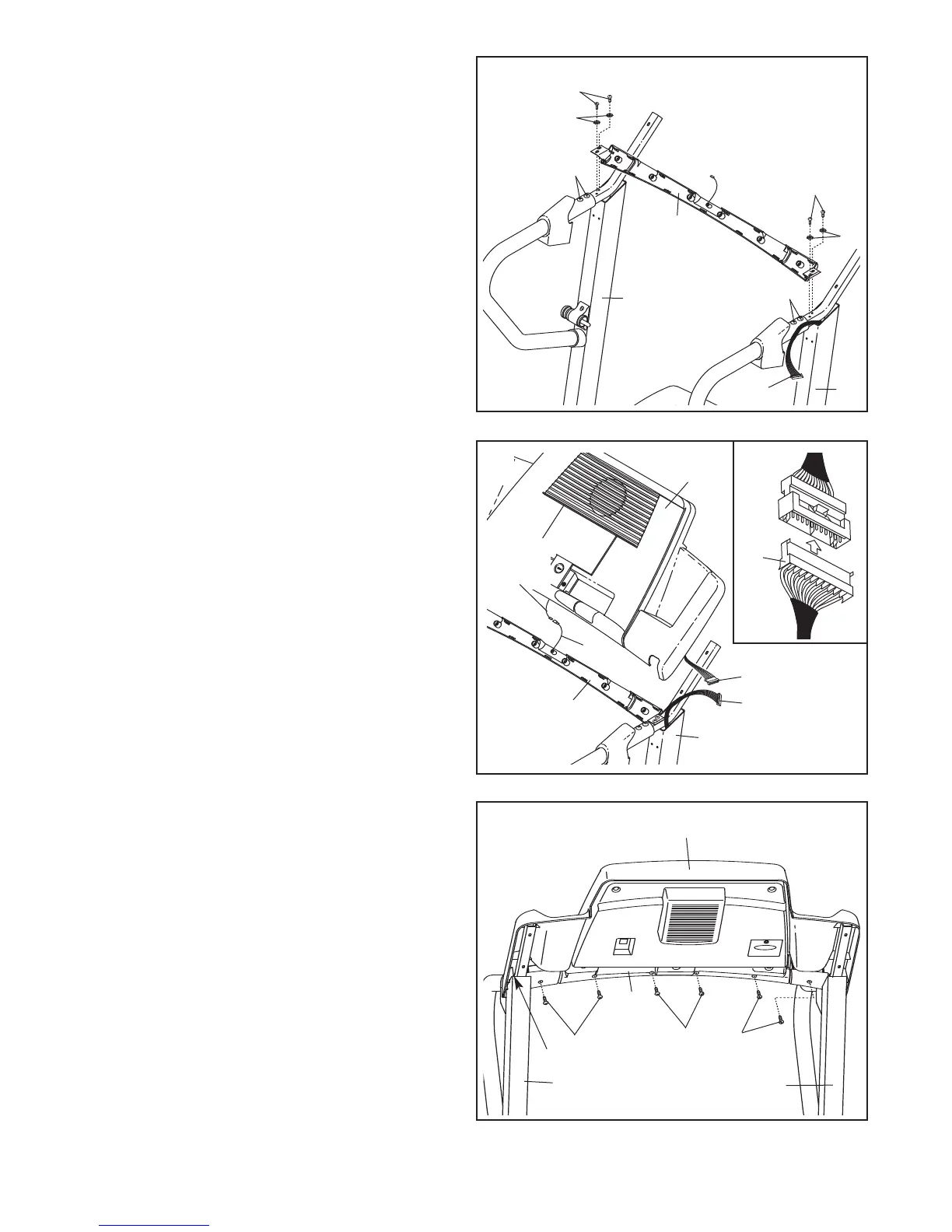
9. While a second person holds the console as-
sembly near the Pulse Bar (66), attach the
Ground Wire (107) on the Pulse Bar to the
ground wire from the console assembly.
Connect the wire from the console assembly to
the Upright Wire (75). Make sure to connect
the connectors properly (see the inset draw-
ing). The connectors should slide together
easily and snap into place. If the connectors
do not slide together easily and snap into place,
turn one connector and then try again. IF THE
CONNECTORS ARE NOT CONNECTED
PROPERLY, THE CONSOLE MAY BE DAM-
AGED WHEN THE POWER IS TURNED ON.
Insert the connectors downward into the Right
Upright (76).
75
Console
Assembly
Wire
76
107
9
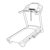
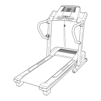
8. Make sure that the Upright Wire (75) is posi-
t
ioned at the side of the post on the Right
Upright (76) as shown.
Orient the Pulse Bar (66) onto the top of the Left
a
nd Right Uprights (70, 76). Attach the Pulse Bar
with four Pulse Bar Screws (64) and four Pulse
Bar Star Washers (65).
Firmly tighten the four
Pulse Bar Screws.
Firmly tighten the four 1 1/4” Bolts (63).
70
64
65
64
65
63
76
66
63
8
75
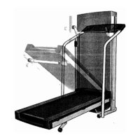
10.Set the console assembly on the Left Upright
(70) and Right Upright (76).
Be careful not to
pinch any wires.
Attach the console assembly to the Pulse Bar
(66) with six 3/4” Screws (23). Start all six 3/4”
Screws, but do not tighten them yet.
23
Console Assembly
23
23
76
75
70
10
Ground
Wire
75
66
66
 Loading...