Disclaimer: All terminals must
be torqued to 5.5Nm.
Installation
Wall Mounted
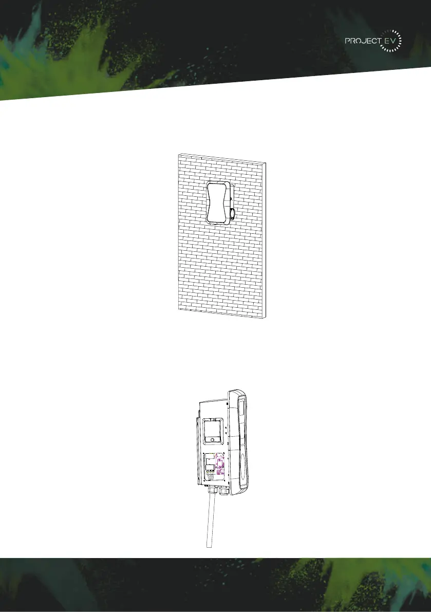
3. Mount the charge point onto the bracket, and fix it with the 2 screws at the bottom of a
charge point. This will secure the charger to the bracket.
4. Remove the side plate, crimp the cables using insulated ferrule’s into terminals provided.
Polarity can be found written on the PCB below the connections. Check the wiring before
powering up - the RCBO is in the top window and may need the reset indicator resetting by
pressing this in before the RCBO can be reset. Once complete, re-fit the access panel.
3XWWKHFKDUJHSRLQWRQWRWKHEUDFNHWDQGIL[LWZLWKWKHVFUHZVDWWKHERWWRPRI
WKHFKDUJHSRLQW7KHLQVWDOODWLRQLVGRQH
&ULPSWKHEHORZVKRZQLQVXODWHGIHUUXOHRUULQJWHUPLQDOVRQWKHHQGRIWKH$&LQSXW
ZLUHV&RQQHFWWKHZLUHVLQWRWKHWHUPLQDOEORFNRIWKHFKDUJHSRLQWDVEHORZ&KHFNWKH
ZLULQJDQGWKHQFORVHWKH5&'LQWKHVLGHZLQGRZ&ORVHWKHVLGHZLQGRZZLWKWKHFRYHU
WKHQWKHZULQJLVGRQH
0RXQWRQDSROH
2SHQWKHSDFNDJLQJRIWKHSROHWDNHRXWWKHSROHDQGPRXQWLQJDFFHVVRULHV
7KHSROHPXVWEHLQVWDOOHGRQDKDUGVXUIDFHFRQFUHWHVXUIDFHLVUHFRPPHQGHGLW
FDQDOVREHPRXQWHGRQDVROLGJURXQG'ULOOKROHVDFFRUGLQJWRWKHUHTXLUHPHQWVPDUNHG
RQWKHLOOXVWUDWLRQIRUIL[LQJH[SDQVLRQEROWV
)L[WKHSROHRQWRWKHKROHVZLWKH[SDQVLRQEROWV7KHLQSXWFDEOHVVKDOOJRLQWRWKH
SROH IURP WKH ERWWRP PLGGOH DUHD DQG FRPH RXW RI LW IURP WKH DUHD EHORZ WKH FDEOH
KRRNHU
3.1.3 Put the charge point onto the bracket, and x it with the 2 screws at the bottom of
the charge point. The installation is done.
3.1.4 Crimp the insulated ferrule or ring terminals on the end of the AC input wires.
Connect the wires into the terminal block of the charge point as below. Check the
wiring and then close the RCD in the side window. Close the side window with the
cover, then the wiring is completed.
3.2.2 The pole must be installed on a hard surface, concrete surface is recommended,
it can also be mounted on a solid ground. Drill holes according to the requirements
marked on the illustration for xing expansion bolts.
3.2.3 Fix the pole onto the holes with expansion bolts. The input cables shall go
into the pole from the bottom middle area and come out of it from the area below the
cable hooker.
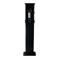
3.2 Mount on a pole
3.2.1 Open the packaging of the pole, take out the pole and mounting accessories.
8 9
3XW WKHFKDUJHSRLQW RQWRWKHEUDFNHW DQGIL[LW ZLWKWKH VFUHZVDWWKHERWWRPRI
WKHFKDUJHSRLQW7KHLQVWDOODWLRQLVGRQH
&ULPSWKHEHORZVKRZQLQVXODWHGIHUUXOHRUULQJWHUPLQDOVRQWKHHQGRIWKH$&LQSXW
ZLUHV&RQQHFWWKHZLUHVLQWRWKHWHUPLQDOEORFNRIWKHFKDUJHSRLQWDVEHORZ&KHFNWKH
ZLULQJDQGWKHQFORVHWKH5&'LQWKHVLGHZLQGRZ&ORVHWKHVLGHZLQGRZZLWKWKHFRYHU
WKHQWKHZULQJLVGRQH
0RXQWRQDSROH
2SHQWKHSDFNDJLQJRIWKHSROHWDNHRXWWKHSROHDQGPRXQWLQJDFFHVVRULHV
7KHSROHPXVWEHLQVWDOOHGRQDKDUGVXUIDFHFRQFUHWHVXUIDFHLVUHFRPPHQGHGLW
FDQDOVREHPRXQWHGRQDVROLGJURXQG'ULOOKROHVDFFRUGLQJWRWKHUHTXLUHPHQWVPDUNHG
RQWKHLOOXVWUDWLRQIRUIL[LQJH[SDQVLRQEROWV
)L[WKHSROHRQWRWKHKROHVZLWKH[SDQVLRQEROWV7KHLQSXWFDEOHVVKDOOJRLQWRWKH
SROH IURP WKH ERWWRP PLGGOH DUHD DQG FRPH RXW RI LW IURP WKH DUHD EHORZ WKH FDEOH
KRRNHU
3.1.3 Put the charge point onto the bracket, and x it with the 2 screws at the bottom of
the charge point. The installation is done.
3.1.4 Crimp the insulated ferrule or ring terminals on the end of the AC input wires.
Connect the wires into the terminal block of the charge point as below. Check the
wiring and then close the RCD in the side window. Close the side window with the
cover, then the wiring is completed.
3.2.2 The pole must be installed on a hard surface, concrete surface is recommended,
it can also be mounted on a solid ground. Drill holes according to the requirements
marked on the illustration for xing expansion bolts.
3.2.3 Fix the pole onto the holes with expansion bolts. The input cables shall go
into the pole from the bottom middle area and come out of it from the area below the
cable hooker.
3.2 Mount on a pole
3.2.1 Open the packaging of the pole, take out the pole and mounting accessories.
8 9
11
 Loading...