3XWWKHFKDUJHSRLQWRQWRWKHEUDFNHWDQGIL[LWZLWKWKHVFUHZVDWWKHERWWRPRI
WKHFKDUJHSRLQW7KHLQVWDOODWLRQLVGRQH
&ULPSWKHEHORZVKRZQLQVXODWHGIHUUXOHRUULQJWHUPLQDOVRQWKHHQGRIWKH$&LQSXW
ZLUHV&RQQHFWWKHZLUHVLQWRWKHWHUPLQDOEORFNRIWKHFKDUJHSRLQWDVEHORZ&KHFNWKH
ZLULQJDQGWKHQFORVHWKH5&'LQWKHVLGHZLQGRZ&ORVHWKHVLGHZLQGRZZLWKWKHFRYHU
WKHQWKHZULQJLVGRQH
0RXQWRQDSROH
2SHQWKHSDFNDJLQJRIWKHSROHWDNHRXWWKHSROHDQGPRXQWLQJDFFHVVRULHV
7KHSROHPXVWEHLQVWDOOHGRQDKDUGVXUIDFHFRQFUHWHVXUIDFHLVUHFRPPHQGHGLW
FDQDOVREHPRXQWHGRQDVROLGJURXQG'ULOOKROHVDFFRUGLQJWRWKHUHTXLUHPHQWVPDUNHG
RQWKHLOOXVWUDWLRQIRUIL[LQJH[SDQVLRQEROWV
)L[WKHSROHRQWRWKHKROHVZLWKH[SDQVLRQEROWV7KHLQSXWFDEOHVVKDOOJRLQWRWKH
SROH IURP WKH ERWWRP PLGGOH DUHD DQG FRPH RXW RI LW IURP WKH DUHD EHORZ WKH FDEOH
KRRNHU
3.1.3 Put the charge point onto the bracket, and x it with the 2 screws at the bottom of
the charge point. The installation is done.
3.1.4 Crimp the insulated ferrule or ring terminals on the end of the AC input wires.
Connect the wires into the terminal block of the charge point as below. Check the
wiring and then close the RCD in the side window. Close the side window with the
cover, then the wiring is completed.
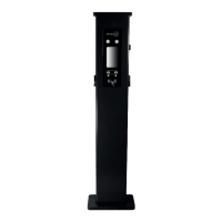
3.2.2 The pole must be installed on a hard surface, concrete surface is recommended,
it can also be mounted on a solid ground. Drill holes according to the requirements
marked on the illustration for xing expansion bolts.
3.2.3 Fix the pole onto the holes with expansion bolts. The input cables shall go
into the pole from the bottom middle area and come out of it from the area below the
cable hooker.
3.2 Mount on a pole
3.2.1 Open the packaging of the pole, take out the pole and mounting accessories.
8 9
Solar Configuration
7KW
For solar features to work, the CT clamp must be installed correctly and the following
settings must be set prior to switching Solar Modes:
- Power Allocation Charge - DIsabled -
- External current sampling wiring method- CT2000 or CT3000
Disclaimer: Please check whether the CT clamp has a 2.0 or 3.0 on the end of the product
code. If there is a 2.0, the current sampling method must be set to CT2000. If there is a 3.0,
the current sampling method must be set to CT3000.
The charge point can work with grid-tied solar system, to detect and use the residual solar
power to charge your car that would. Otherwise be fed back to the grid. This can help
increase the self-usage rate of the solar system and reduce electricity bill for the household.
The charge point supports 3 charging mode with grid-tied PV system: FAST, ECO and ECO+
Introduction to the 3 modes for solar charge
FAST Mode: Charge at the rated power, the car can be fully charged in the shortest time at
this mode.
ECO Mode:
(1) The charge point uses only surplus solar power to charge car when the surplus solar
power is greater than 1.76kw (6 amps).
(2) When surplus solar power is lower than 1.76kw, the charge point will charge at 1.8kW
and use grid power to offset the shortage part.
ECO+ Mode:
(1) Dynamically adjust the charging power according to the available surplus power. If
there is no enough excess solar power(>1.8kW), the charging will stop until there is residual
solar power greater than 1.8kW again.
(2) It is allowable to set a value between 0-1.76kW. When the power import from grid
exceeds this preset threshold, charging will cease. When solar export exceeds this value, the
charging will resume.
15
5LJKWFOLFNRQ/RFDO$UHD&RQQHFWLRQDQGFOLFNRQ3URSHUWLHV
6HOHFW,QWHUQHW3URWRFRO9HUVLRQ7&3,3YDQGFOLFNRQ3URSHUWLHV
6HOHFW8VHWKHIROORZLQJ,3DGGUHVVDQGHQWHUWKH,3DGGUHVV6XEQHW0DVN'HIDXOW
*DWHZD\&OLFN2.DQGFORVHWKH/RFDO$UHD&RQQHFWLRQSURSHUWLHVZLQGRZ
F &KHFN ZKDW ZHE EURZVHU LV EHLQJ XVHG LW¶V VXJJHVWHG WR XVH )LUHIR[ RU ,( &KURPH
FDQQRWEHXVHGWRXSGDWHILUPZDUH
G &KHFNLI\RXKDYHLQSXWWKHFRPSOHWHFRQWHQWZKLFKLVKWWS LQWKH
DGGUHVVILHOGGRQRWOHDYHRXWWKHKWWSRUWKH³´
H 6RPHWLPHV\RXPD\QHHGWRUHVWDUWWKHFKDUJHUWRDFFHVVLWVSDUDPHWHUVHWWLQJSDJH
I ,I \RX KDYH FKDQJHG WKH FKDUJHU¶V ,3 WR RWKHU YDOXH DQG FDQQRW UHPHPEHU \RX FDQ
UHVWRUHWKHFKDUJHUWRIDFWRU\VHWWLQJE\ORQJSUHVVWKHUHVHWEXWWRQ7KHQ\RXFDQDFFHVV
LWXVLQJKWWS
3
OHDVHQRWH$IWHUUHVWRULQJWKHFKDUJHUWRIDFWRU\VHWWLQJ\RX¶OOQHHGWRUHVHWWKHFKDUJHU
,'DQGVHUYHUXUORWKHUZLVHWKHFKDUJHUZRQ¶WEHFRQQHFWHGWRWKHEDFNRIILFHVHUYHU
5HVHWEXWWRQ
(3). Right-click on Local Area Connection and click on Properties.
(4). Select Internet Protocol Version 4 (TCP/IPv4) and click on Properties.
(5). Select “Use the following IP address” and enter the IP address, Subnet Mask,
Default Gateway. Click OK and close the Local Area Connection properties window.
c. Check which web browser is being used, it’s suggested you use Firefox or IE.
Chrome cannot be used to update rmware.
d. Check if you have input the complete path, which is http://192.168.1.5:8080, in the
address eld, do not leave out the http:// or the“:8080”.
e. You may need to restart the charger to access its parameter setting page.
f. If you have changed the charger’s IP to another value but cannot remember it, you
can restore the charger to factory setting by pressing and holding the reset button.
Then you can access it using http://192.168.1.5:8080.
Please note: After restoring the charger to factory setting, you need to reset the
charger ID and server url, or the charger won’t be connected to the back-oce server.
32 33
 Loading...