)L[WKHPRXQWLQJEUDFNHWRQWRWKHSROH
3RVLWLRQ WKH FKDUJH SRLQW RQWR WKH EUDFNHWDQG VHFXUH LWRQ WKH EUDFNHWZLWK WKH
VFUHZV
&ULPSWKHEHORZVKRZQLQVXODWHGIHUUXOHRUULQJWHUPLQDOVRQWKHHQGRIWKH$&LQSXW
ZLUHV&RQQHFWWKHZLUHVLQWRWKHWHUPLQDOEORFNRIWKHFKDUJHSRLQWDVEHORZ&KHFNWKH
ZLULQJDQGWKHQFORVHWKH5&'LQWKHVLGHZLQGRZ&ORVHWKHVLGHZLQGRZZLWKWKHFRYHU
WKHQWKHZULQJLVGRQH
,9 3DUDPHWHUVHWWLQJ
$IWHUWKHLQVWDOODWLRQDQGZLULQJLVGRQHFRQQHFWWKH&KDUJHUWRDFRPSXWHUDQGFRQILJXUH
SDUDPHWHUVYLDWKHZHEEURZVHURIWKHFRPSXWHUWKHQWKH&KDUJHUFDQEHUHDG\IRUXVH
6HWFRPSXWHU¶V,3
7KH &KDUJHU¶V GHIDXOW ,3 DGGUHVV LV 7R DFFHVV WKH SDUDPHWHU VHWWLQJ
LQWHUIDFH \RX¶OO QHHG WR ILUVW VHW WKH FRPSXWHU¶V ,3 WR [ [ FDQ EH DQ\
YDOXHEHWZHHQDQGH[FHSWIRUHJ
7RVHWDVWDWLF,3RQ\RXU:LQGRZVFRPSXWHU
&OLFN6WDUW0HQX!&RQWURO3DQHO!1HWZRUN DQG 6KDULQJ &HQWHU)RU:LQGRZVDQG
KLJKHUVHDUFKIRUDQGRSHQ&RQWURO3DQHODQGVHOHFW1HWZRUNDQG,QWHUQHW
&OLFN&KDQJHDGDSWHUVHWWLQJV
IV. Parameter setting
After the installation and wiring is done, connect the Charger to a computer and
congure parameters via the web browser of the computer. The charger is then ready
for use.
4.1 Set computer’s IP
The Charger’s default IP address is 192.168.1.5. To access the parameter setting
interface, you’ll need to rst set the computer’s IP to 192.168.1.x (x can be any value
between 1 and 255 except for 5, e.g. 192.168.1.10).
To set a static IP on your Windows computer:
1. Click Start Menu > Control Panel > Network and Sharing Center. (For Windows 8 and
higher, search for and open Control Panel and select Network and Internet).
2. Click Change adapter settings.
3.2.4 Fix the mounting bracket onto the pole.
3.2.5 Position the charge point onto the bracket and secure it on the bracket with the
2 screws.
3.2.6 Crimp the insulated ferrule or ring terminals on the end of the AC input wires.
Connect the wires into the terminal block of the charge point as below. Check the
wiring and then close the RCD in the side window. Close the side window with the
cover, then the wiring is completed.
10 11
3XW WKHFKDUJHSRLQW RQWRWKHEUDFNHW DQGIL[LW ZLWKWKH VFUHZVDWWKHERWWRPRI
WKHFKDUJHSRLQW7KHLQVWDOODWLRQLVGRQH
&ULPSWKHEHORZVKRZQLQVXODWHGIHUUXOHRUULQJWHUPLQDOVRQWKHHQGRIWKH$&LQSXW
ZLUHV&RQQHFWWKHZLUHVLQWRWKHWHUPLQDOEORFNRIWKHFKDUJHSRLQWDVEHORZ&KHFNWKH
ZLULQJDQGWKHQFORVHWKH5&'LQWKHVLGHZLQGRZ&ORVHWKHVLGHZLQGRZZLWKWKHFRYHU
WKHQWKHZULQJLVGRQH
0RXQWRQDSROH
2SHQWKHSDFNDJLQJRIWKHSROHWDNHRXWWKHSROHDQGPRXQWLQJDFFHVVRULHV
7KHSROHPXVWEHLQVWDOOHGRQDKDUGVXUIDFHFRQFUHWHVXUIDFHLVUHFRPPHQGHGLW
FDQDOVREHPRXQWHGRQDVROLGJURXQG'ULOOKROHVDFFRUGLQJWRWKHUHTXLUHPHQWVPDUNHG
RQWKHLOOXVWUDWLRQIRUIL[LQJH[SDQVLRQEROWV
)L[WKHSROHRQWRWKHKROHVZLWKH[SDQVLRQEROWV7KHLQSXWFDEOHVVKDOOJRLQWRWKH
SROH IURP WKH ERWWRP PLGGOH DUHD DQG FRPH RXW RI LW IURP WKH DUHD EHORZ WKH FDEOH
KRRNHU
3.1.3 Put the charge point onto the bracket, and x it with the 2 screws at the bottom of
the charge point. The installation is done.
3.1.4 Crimp the insulated ferrule or ring terminals on the end of the AC input wires.
Connect the wires into the terminal block of the charge point as below. Check the
wiring and then close the RCD in the side window. Close the side window with the
cover, then the wiring is completed.
3.2.2 The pole must be installed on a hard surface, concrete surface is recommended,
it can also be mounted on a solid ground. Drill holes according to the requirements
marked on the illustration for xing expansion bolts.
3.2.3 Fix the pole onto the holes with expansion bolts. The input cables shall go
into the pole from the bottom middle area and come out of it from the area below the
cable hooker.
3.2 Mount on a pole
3.2.1 Open the packaging of the pole, take out the pole and mounting accessories.
8 9
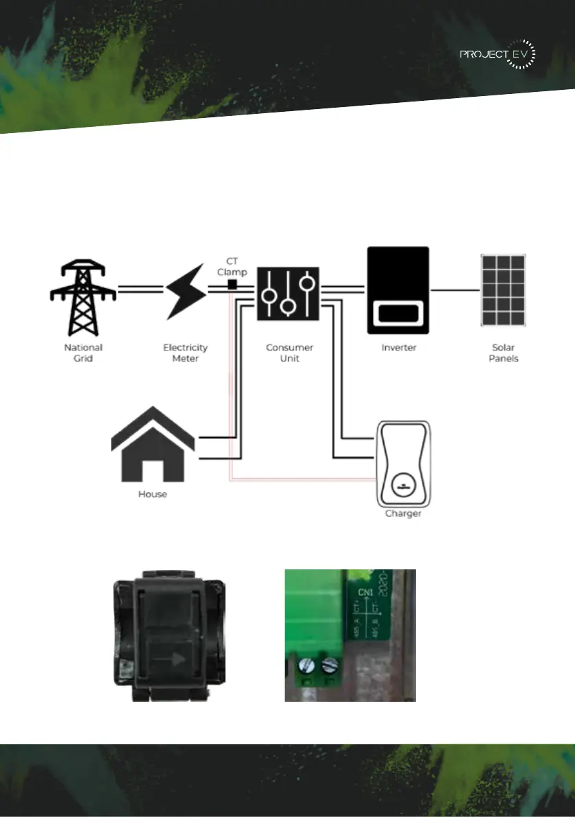
Installation
CT Clamp
To monitor the real-time power import and export, a CT clamp is needed for this function
to work properly. The CT Clamp is needed to operate and use, both solar and dynamic load
balancing only.
Note: CT Clamp wiring can be extended up to 50m using Cat5e cable.
The CT clamp
connects to the
front right
connector plug.
Red connects to
the left and white
to the right. If
unsure check
wiring diagram
on the PCB next
to the connection
blocks.
For the CT
clamp to work
correctly the
‘Arrow’ must
point towards
the flow of
electric this is
from the meter
towards the
consumer unit.
14
5LJKWFOLFNRQ/RFDO$UHD&RQQHFWLRQDQGFOLFNRQ3URSHUWLHV
6HOHFW,QWHUQHW3URWRFRO9HUVLRQ7&3,3YDQGFOLFNRQ3URSHUWLHV
6HOHFW8VHWKHIROORZLQJ,3DGGUHVVDQGHQWHUWKH,3DGGUHVV6XEQHW0DVN'HIDXOW
*DWHZD\&OLFN2.DQGFORVHWKH/RFDO$UHD&RQQHFWLRQSURSHUWLHVZLQGRZ
F &KHFN ZKDW ZHE EURZVHU LV EHLQJ XVHG LW¶V VXJJHVWHG WR XVH )LUHIR[ RU ,( &KURPH
FDQQRWEHXVHGWRXSGDWHILUPZDUH
G &KHFNLI\RXKDYHLQSXWWKHFRPSOHWHFRQWHQWZKLFKLVKWWS LQWKH
DGGUHVVILHOGGRQRWOHDYHRXWWKHKWWSRUWKH³´
H 6RPHWLPHV\RXPD\QHHGWRUHVWDUWWKHFKDUJHUWRDFFHVVLWVSDUDPHWHUVHWWLQJSDJH
I ,I \RX KDYH FKDQJHG WKH FKDUJHU¶V ,3 WR RWKHU YDOXH DQG FDQQRW UHPHPEHU \RX FDQ
UHVWRUHWKHFKDUJHUWRIDFWRU\VHWWLQJE\ORQJSUHVVWKHUHVHWEXWWRQ7KHQ\RXFDQDFFHVV
LWXVLQJKWWS
3
OHDVHQRWH$IWHUUHVWRULQJWKHFKDUJHUWRIDFWRU\VHWWLQJ\RX¶OOQHHGWRUHVHWWKHFKDUJHU
,'DQGVHUYHUXUORWKHUZLVHWKHFKDUJHUZRQ¶WEHFRQQHFWHGWRWKHEDFNRIILFHVHUYHU
5HVHWEXWWRQ
(3). Right-click on Local Area Connection and click on Properties.
(4). Select Internet Protocol Version 4 (TCP/IPv4) and click on Properties.
(5). Select “Use the following IP address” and enter the IP address, Subnet Mask,
Default Gateway. Click OK and close the Local Area Connection properties window.
c. Check which web browser is being used, it’s suggested you use Firefox or IE.
Chrome cannot be used to update rmware.
d. Check if you have input the complete path, which is http://192.168.1.5:8080, in the
address eld, do not leave out the http:// or the“:8080”.
e. You may need to restart the charger to access its parameter setting page.
f. If you have changed the charger’s IP to another value but cannot remember it, you
can restore the charger to factory setting by pressing and holding the reset button.
Then you can access it using http://192.168.1.5:8080.
Please note: After restoring the charger to factory setting, you need to reset the
charger ID and server url, or the charger won’t be connected to the back-oce server.
32 33
 Loading...