Installation
Pole Mounted
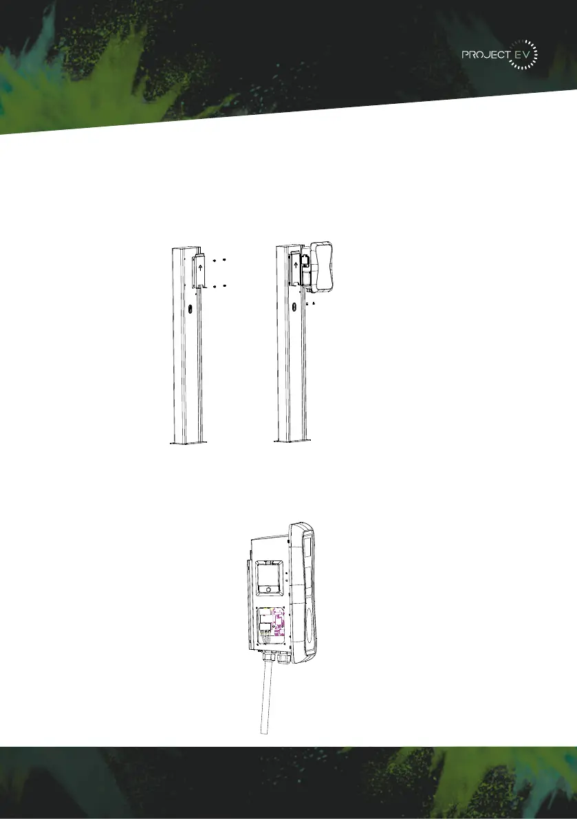
4. Position the charge point bracket and secure it on the pole with the 4 screws provided
with pole. Once the bracket is secure, mount the charger onto the bracket and fix it with
the 2 screws at the bottom of the charge point. This will secure the charger to the bracket.
5. Remove the side plate, crimp the cables using insulated ferrule’s into terminals provided.
Polarity can be found written on the PCB below the connection’s. Check the wiring before
powering up - the RCBO is in the top window and may need the reset indicator resetting by
pressing this in before the RCBO can be reset. Once complete, re-fit the access panel.
)L[WKHPRXQWLQJEUDFNHWRQWRWKHSROH
3RVLWLRQ WKH FKDUJH SRLQW RQWR WKH EUDFNHWDQG VHFXUH LWRQ WKH EUDFNHWZLWK WKH
VFUHZV
&ULPSWKHEHORZVKRZQLQVXODWHGIHUUXOHRUULQJWHUPLQDOVRQWKHHQGRIWKH$&LQSXW
ZLUHV&RQQHFWWKHZLUHVLQWRWKHWHUPLQDOEORFNRIWKHFKDUJHSRLQWDVEHORZ&KHFNWKH
ZLULQJDQGWKHQFORVHWKH5&'LQWKHVLGHZLQGRZ&ORVHWKHVLGHZLQGRZZLWKWKHFRYHU
WKHQWKHZULQJLVGRQH
,9 3DUDPHWHUVHWWLQJ
$IWHUWKHLQVWDOODWLRQDQGZLULQJLVGRQHFRQQHFWWKH&KDUJHUWRDFRPSXWHUDQGFRQILJXUH
SDUDPHWHUVYLDWKHZHEEURZVHURIWKHFRPSXWHUWKHQWKH&KDUJHUFDQEHUHDG\IRUXVH
6HWFRPSXWHU¶V,3
7KH &KDUJHU¶V GHIDXOW ,3 DGGUHVV LV 7R DFFHVV WKH SDUDPHWHU VHWWLQJ
LQWHUIDFH \RX¶OO QHHG WR ILUVW VHW WKH FRPSXWHU¶V ,3 WR [ [ FDQ EH DQ\
YDOXHEHWZHHQDQGH[FHSWIRUHJ
7RVHWDVWDWLF,3RQ\RXU:LQGRZVFRPSXWHU
&OLFN6WDUW0HQX!&RQWURO3DQHO!1HWZRUN DQG 6KDULQJ &HQWHU)RU:LQGRZVDQG
KLJKHUVHDUFKIRUDQGRSHQ&RQWURO3DQHODQGVHOHFW1HWZRUNDQG,QWHUQHW
&OLFN&KDQJHDGDSWHUVHWWLQJV
IV. Parameter setting
After the installation and wiring is done, connect the Charger to a computer and
congure parameters via the web browser of the computer. The charger is then ready
for use.
4.1 Set computer’s IP
The Charger’s default IP address is 192.168.1.5. To access the parameter setting
interface, you’ll need to rst set the computer’s IP to 192.168.1.x (x can be any value
between 1 and 255 except for 5, e.g. 192.168.1.10).
To set a static IP on your Windows computer:
1. Click Start Menu > Control Panel > Network and Sharing Center. (For Windows 8 and
higher, search for and open Control Panel and select Network and Internet).
2. Click Change adapter settings.
3.2.4 Fix the mounting bracket onto the pole.
3.2.5 Position the charge point onto the bracket and secure it on the bracket with the
2 screws.
3.2.6 Crimp the insulated ferrule or ring terminals on the end of the AC input wires.
Connect the wires into the terminal block of the charge point as below. Check the
wiring and then close the RCD in the side window. Close the side window with the
cover, then the wiring is completed.
10 11
3XW WKHFKDUJHSRLQW RQWRWKHEUDFNHW DQGIL[LW ZLWKWKH VFUHZVDWWKHERWWRPRI
WKHFKDUJHSRLQW7KHLQVWDOODWLRQLVGRQH
&ULPSWKHEHORZVKRZQLQVXODWHGIHUUXOHRUULQJWHUPLQDOVRQWKHHQGRIWKH$&LQSXW
ZLUHV&RQQHFWWKHZLUHVLQWRWKHWHUPLQDOEORFNRIWKHFKDUJHSRLQWDVEHORZ&KHFNWKH
ZLULQJDQGWKHQFORVHWKH5&'LQWKHVLGHZLQGRZ&ORVHWKHVLGHZLQGRZZLWKWKHFRYHU
WKHQWKHZULQJLVGRQH
0RXQWRQDSROH
2SHQWKHSDFNDJLQJRIWKHSROHWDNHRXWWKHSROHDQGPRXQWLQJDFFHVVRULHV
7KHSROHPXVWEHLQVWDOOHGRQDKDUGVXUIDFHFRQFUHWHVXUIDFHLVUHFRPPHQGHGLW
FDQDOVREHPRXQWHGRQDVROLGJURXQG'ULOOKROHVDFFRUGLQJWRWKHUHTXLUHPHQWVPDUNHG
RQWKHLOOXVWUDWLRQIRUIL[LQJH[SDQVLRQEROWV
)L[WKHSROHRQWRWKHKROHVZLWKH[SDQVLRQEROWV7KHLQSXWFDEOHVVKDOOJRLQWRWKH
SROH IURP WKH ERWWRP PLGGOH DUHD DQG FRPH RXW RI LW IURP WKH DUHD EHORZ WKH FDEOH
KRRNHU
3.1.3 Put the charge point onto the bracket, and x it with the 2 screws at the bottom of
the charge point. The installation is done.
3.1.4 Crimp the insulated ferrule or ring terminals on the end of the AC input wires.
Connect the wires into the terminal block of the charge point as below. Check the
wiring and then close the RCD in the side window. Close the side window with the
cover, then the wiring is completed.
3.2.2 The pole must be installed on a hard surface, concrete surface is recommended,
it can also be mounted on a solid ground. Drill holes according to the requirements
marked on the illustration for xing expansion bolts.
3.2.3 Fix the pole onto the holes with expansion bolts. The input cables shall go
into the pole from the bottom middle area and come out of it from the area below the
cable hooker.
3.2 Mount on a pole
3.2.1 Open the packaging of the pole, take out the pole and mounting accessories.
8 9
13
G 6RPH URXWHUV KDYH :L)L RQH LV *+] WKH RWKHU LV *+] 0RVW KRPHV MXVW XVH WKH
*+]:L)LDVWKHLUGHIDXOW:L)L%XWWKHFKDUJHUFDQRQO\FRQQHFWWRWKH*+]:L)L6RLI
WKH FKDUJHU FDQ FRQQHFW WR \RXUPRELOH SKRQH KRWVSRWEXW FDQQRW FRQQHFW WRWKH KRPH
:L)L3OHDVHFKHFNZLWKWKHKRPHRZQHURUFKHFNRQWKHLUURXWHUWRVHHLI\RXDUHXVLQJWKH
*+]:L)L3OHDVHGRXVHWKH*+]:L)LIRUFKDUJHUFRQQHFWLRQ
H &KHFNLI WKH FKDUJHU LV VWLOO FRQQHFWHG WR WKH FRPSXWHU 3OHDVH XQSOXJ LW IURPFRPSXWHU
RWKHUZLVHWKHFKDUJHUZRQªWFRQQHFWWRWKHEDFNRIILFHVHUYHU
I &KHFN LI VHUYHU DGGUHVV LV FRUUHFW LQ WKH§6HUYHU 85/¨ ILHOG 7KH FRUUHFW VHWWLQJ LV
ZVFKDUJHJURZDWWFRPRFSSZV
&DQQRWDFFHVVSDUDPHWHUVHWWLQJSDJH
&OLFN 6WDUW 0HQX!&RQWURO 3DQHO!1HWZRUN DQG 6KDULQJ &HQWHU )RU :LQGRZV DQG
KLJKHUVHDUFKIRUDQGRSHQ&RQWURO3DQHODQGVHOHFW1HWZRUNDQG,QWHUQHW
7RVHWDVWDWLF,3RQ\RXU:LQGRZVFRPSXWHU
A &KHFNLI\RXKDYHFRQQHFWHGWKHFKDUJHUWR\RXUFRPSXWHU
B &KHFNLI\RXKDYHFKDQJHWKHFRPSXWHUªV,3WR[[FDQEHDQ\YDOXHEHWZHHQ
DQGH[FHSW
&OLFN&KDQJHDGDSWHUVHWWLQJV
d. Some routers have 2 WiFi signals, one is 2.4GHz, the other is 5GHz. Most homes
use the 5GHz WiFi as their default WiFi but the charger can only connect to the 2.4GHz
WiFi. So if the charger can connect to your mobile phone hotspot, but cannot connect
to the home WiFi please check the router to see if you are using the 5GHz WiFi. Use the
2.4GHz WiFi for charger connection.
e. Check if the charger is still connected to the computer. Please unplug it from
computer otherwise the charger won’t connect to the back-oce server.
f. Check if server address is correct in the“Server URL” eld. The correct setting is :
ws://ess-charge.atesspower.com:80/ocpp/ws
7.4 Cannot access parameter setting page
a. Check if you have connected the charger to your computer,
b. Check if you have changed the computer’s IP to 192.168.1.x (x can be any value
between 1 and 255 except 5).
To set a static IP on your Windows computer:
(1). Click Start Menu>Control Panel>Network and Sharing Center. (For Windows 8 and
higher, search for and open Control Panel and select Network and Internet).
(2). Click Change adapter settings.
30 31
 Loading...