7
ECL
1
2
4
5
3
7
6
8
9
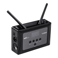
12
11
13
10
14 15
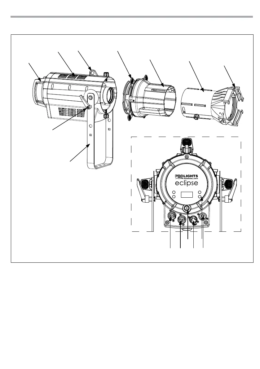
1.4 OPERATING ELEMENTS AND CONNECTIONS
Fig.2
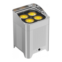
1. MOUNTING BRACKET
2. LOCKING KNOB for the mounting bracket
3. HANDLE
4. ECL
5. SAFETY EYE to attach safety cable.
6. SHUTTER
7. ECLMP - Aluminium middle part
8. OPTIC
9. FILTER FRAME
10. FUSE OLDER in the event of breakage, always
replace the fuse with the same type and
rating (T3.15A).
11. CONTROL PANEL with display and 4 button
used to access the control panel functions
and manage them.
12. POWER IN (PowerCON IN): for connection to a
socket (100-240V~/50-60Hz) via the supplied
mains cable.
13. POWER OUT (PowerCON OUT): connect to
supply power to the next unit.
14. DMX OUT (5-pole XLR):
1 = ground, 2 = DMX-, 3 = DMX+, 4 N/C, 5 N/C
15. DMX IN (5-pole XLR):
1 = ground, 2 = DMX-, 3 = DMX+, 4 N/C, 5 N/C
Rear panel