RDM0012 Issue 1 AA Page 20 of 35 © Protec Fire Detection PLC 2017
4.3 Mounting
Use the installation template, provided at the end of the document, to mark out the fixing
points, then drill and plug the holes as marked.
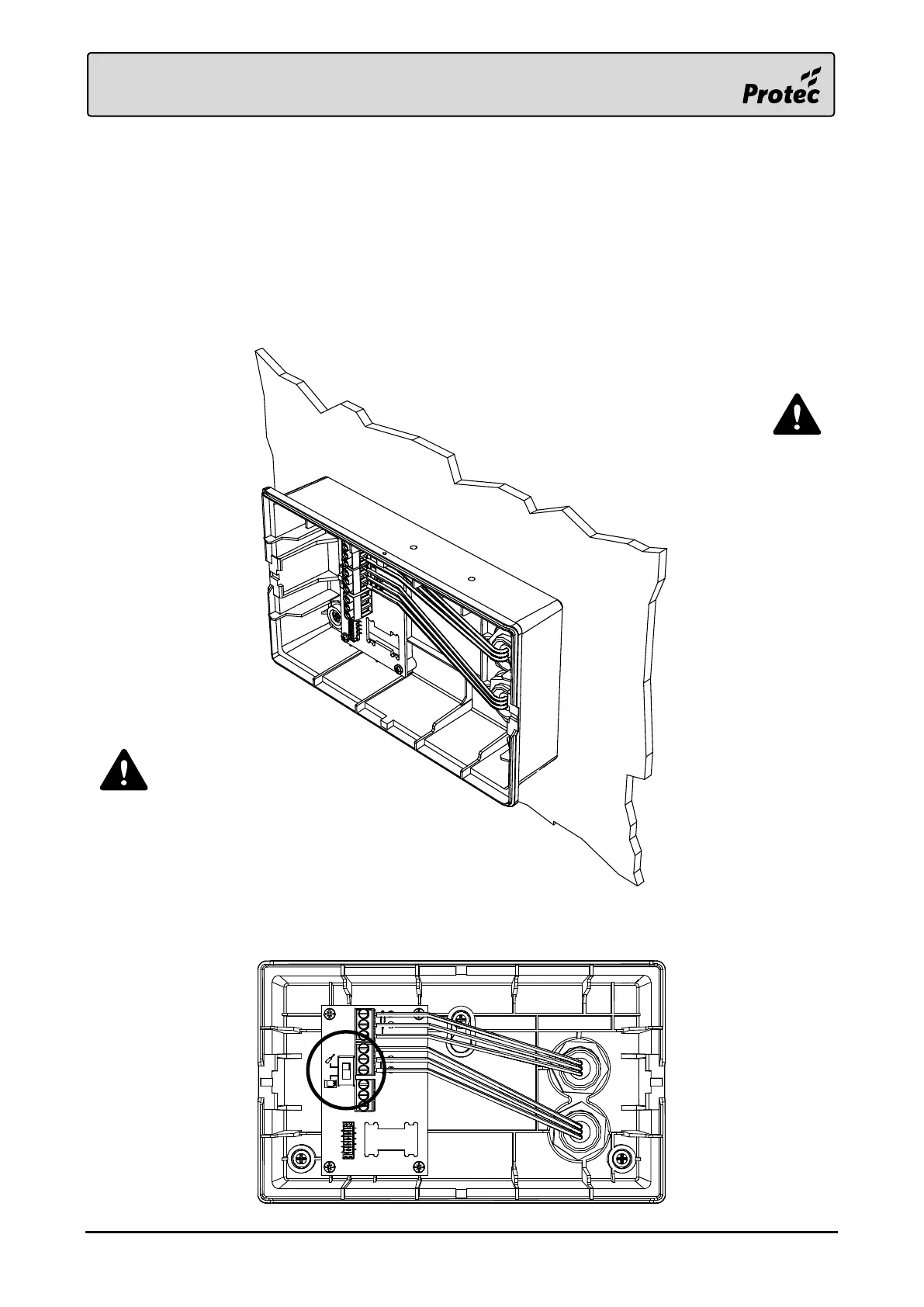
Using a 20mm hole-saw, drill the required entry points in the back box. Feed the Loop wiring
into the enclosure using suitable glands.
Strip the cable sheaths at the entrance to the box, only run individual conductors within the
box.
Carefully screw the back box to the fixing points, taking care not to overtighten the screws.
Terminate the conductors to the correct terminals.
Set the loop continuity switch on the terminal board to the commissioning position whilst the
front panel is removed.
Only use the cable entry
points provided.
Ensure conductors are as flat to the back
box as possible, whilst respecting the
cable manufacturer’s recommended
minimum bend radius.