28 OPTIMAX
®
Trouble Shooting
®
3.6 Processing time and developer temperature relation
The following chart demonstrates guide value relations between developer temper-
atures and processing times. Variations are possible depending on the various films
and chemicals. Changing the transport speed see 3.7.
3.7 Changing the transport speed
The processing speed can be changed by changing the gear wheels. To do this the
tanks need to be emptied and the machine be turned over. After removing the drive
motor the chain gears can be changed. Please note that the jumper on the PCB
needs to be placed to the indicated position.
Following gear combinations are available:
t = Processing time in seconds
Gm = Chain wheel on motor shaft
Gs = Chain wheel on drive shaft
4Bath
4.1 No circulation in bath
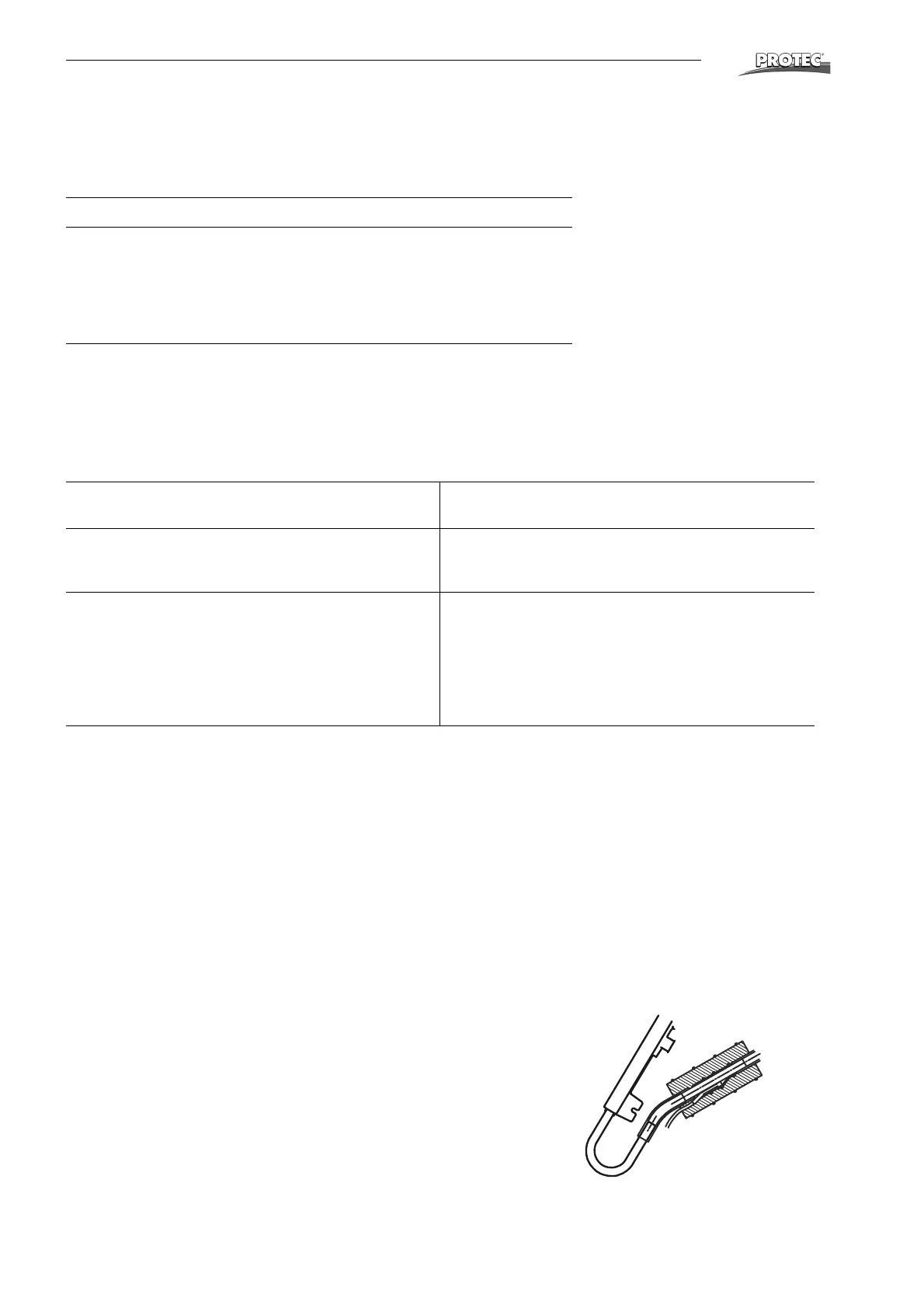
• Circulation pump works but no circulation in bath: Air lock in heating and cir-
culation system. Ventilate pump (see Page 9).
• Particles in the pump chamber. The pump chamber can be easily opened by
removing the four clips. When closing again ensure that the rubber seal is
positioned correctly and not damaged.
• Check connection of pump, circulation pump possibly defective.
Processing time "Dry to Dry" Developer temperature
105 s 32 °C - 34 °C
118 s 32 °C - 34 °C
135 s 31 °C - 33 °C
143 s 30 °C - 32 °C
167 s 30 °C - 32 °C
220-240 V, 50/60 Hz-Versions
110-120 V, 50 Hz-Versions
110-120 V, 60 Hz Versions
tGmGsJumper
position
Devel-
oper time
(s)
Infeed
speed
(cm/min)
tGmGsJumper
position
Devel-
oper time
(s)
Infeed
speed
(in/min)
105 t=17 t=16 2-3 29 48 105
(90)
14 16 2-3 29 18.9
118 t=16 t=17 1-2 32 43 113 14 17 2-3 31 17.6
135 t=14 t=17 1-2 37 37 124 12 16 1-2 34 16.0
143 t=14 t=18 removed 39 35 132 12 17 1-2 36 15.0
167 t=12 t=18 removed 46 30 139 12 18 1-2 38 14.3
4.2 Developer temperature too high
• Check attachment of temperature sensor. This should be firmly positioned on
tube and completely covered with foam rubber.
• Check sensor: At ambient temperature voltage between pin 3 (green) and
pin 2 (brown) must be between 0.1 and 0.5 V.
• If the sensor has no fault then the microprocessor board is defective.