13
5.0 Typical Installations (cont’d)
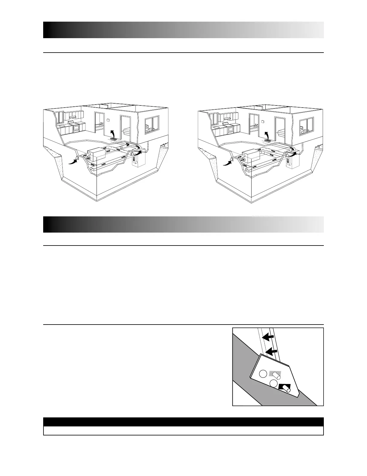
5.3 S
IMPLIFIED
(V
OLUME
V
ENTILATION
)
(For homes with forced air heating. See figure 3 or 4.)
Fresh air and exhaust air flow through the furnace ducts wich simplifies the installation.
The use of bathroom fans and a range hood is suggested to better exhaust stale air.
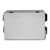
NOTE: For the installation type shown in figure 4, furnace blower must be running when the unit is in operation.
VH
2
figure 3
OR
VH
2
figure 4
See 6.5.3
for details
6.0 Installation
See 6.5.3
for details
I
NSPECT THE
C
ONTENTS OF THE
B
OX
• Inspect the exterior of the unit for shipping damage. Ensure that there is no damage to the door, door
latches, door hinges, dampers, duct collars, cabinet, etc.
• Inspect the interior of the unit for damage. Ensure that the fan motor assembly, recovery core,
insulation, dampers, damper actuator and drain pan are all intact.
• If the unit was damaged during shipping, contact your local distributor. (Claim must be made within
24 hours after delivery.)
• Use checklist included with the unit to ensure that no parts are missing.
6.1 A
DJUSTING THE
D
AMPER
R
OD
(F
OR
ERV
S
I
NSTALLED IN
W
ARM
R
EGIONS
)
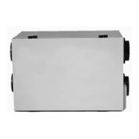
Refer to Section 4.2 and observe the difference in the damper position
at the right in diagrams Defrost Mode 1 and Defrost Mode 2:
for Defrost Mode 1 the damper is completely closed, whereas for
Defrost Mode 2 the damper is half closed. At the factory, all ERVs are
assembled for defrost Mode 2. Therefore, if your installation is for an
ERV in a warm region (zone D as defined in Section 3), the rod must
be moved to position 1 (see figure 5).
NOTE: Before attempting to change the position of the damper rod, place
the unit on a table for easy access and remove the recovery core.
V
1
1
2
figure 5
CAUTION
This is a delicate operation: to avoid injury proceed carefully and use the appropriate tools.