23
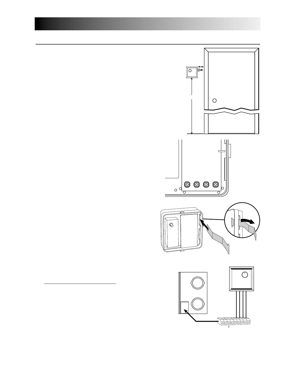
3- Install the wall control 60 inches (1.5 m) from the floor and
leave a free space of at least 2 inches (5 cm) to the right of
the control to allow user to slide out the control instructions.
Use the template provided in the control box to position the
wire hole and the screw holes. Use the screws and the plastic
anchors provided in the installation kit to secure the control.
(See figure 16.)
4- Connect the wires to the main control.
(See figure 17.)
5- Make sure the instruction pull-out is in the occupant’s
language. If not, turn it to the other side.
(See figure 18.)
6- Reinstall the cover plate and the button(s).
7- Connect the wires to their corresponding position
inside the electrical compar
tment. Make sure the
connections of the unit and of the wall control
correspond exactly. (See figure 19)
8- Connect the optional control (if applicable) by
referring to Section 8.3.
9- Do the appropriate connection to the furnace (if
applicable) by referring to Section 8.4.
10- NOTE: If you are in a cold region (Zone A, as defined in Section 3.0), set up “extended defrost” by removing
jumper JU1F on the main circuit board inside the electrical compartment (see Section 9.0).
11- Plug in the unit and do the “overall verification” of the system as described in Section 11.0.
8.0
Installation of the Controls (cont’d)
VE0084
"
1.
2"
5 cm
VD0025
ECONOMY / VALUE
VC0061
8.2 I
NSTALLATION OF THE
M
AIN
C
ONTROL
(cont’d)
figure 16
figure 17
figure 18
figure 19