14
6.0 Installation (cont’d)
6.2 L
OCATING AND
M
OUNTING THE
U
NIT
Choose an appropriate location for the unit:
• Within an area of the house where the temperature is above 10°C /
50°F (basement, attic, furnace room, laundry room, etc.).
• Away from living areas (dining room, living room, bedroom), if possible.
• So as to provide easy access to the interior cabinet and to the
control panel on the right hand side of the unit.
• Close to an exterior wall, so as to limit the length of the insulated
flexible duct to and from the unit.
• Close to a drain. If no drain is close by, use a pail to collect run-off.
• Away from hot chimneys, electrical panel and other fire hazards.
• Allow for a power source (110 V standard outlet).
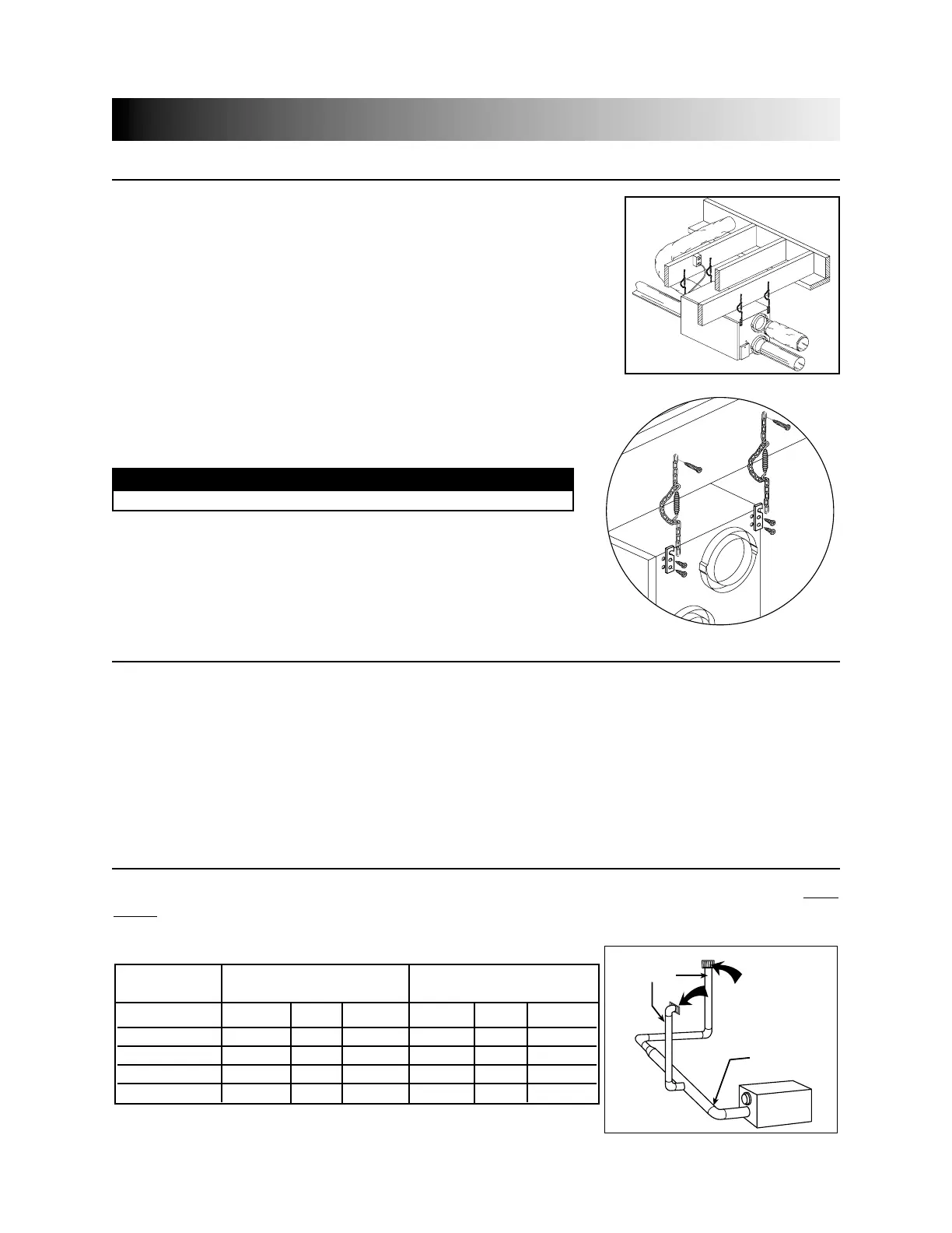
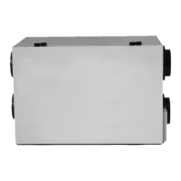
Hang the unit to ceiling joists with the 4 chains and springs
provided (see figures 6 and 7).
VD0064
VD0038
figure 6
figure 7
CAUTION
Make sure the unit is level.
6.3 P
LANNING OF THE
D
UCTWORK
a) Follow the instructions in Section 6.4 below to determine the appropriate duct diameters for your system.
b) Keep it simple. Plan for a minimum number of bends and joints. Keep the length of insulated duct to a
minimum.
c) Do not use wall cavities as ducts. Do not use branch lines smaller than 4” (102 mm) Ø.
d) Do not ventilate crawl spaces or cold rooms. Do not attempt to recover the exhaust air from a dryer or
a range hood. This would cause clogging of the recovery module. Use sheet metal for the kitchen
exhaust duct.
e) Be sure to plan for at least one exhaust register on the highest lived-in level of the house if it has 2 floors
or more.
6.4 C
ALCULATING THE
D
UCT
S
IZE
Use the table below to ensure that the ducts you intend to install will be carrying air flows at or
under the recommended values. Avoid installing ducts that will have to carry air flows near the
maximum values and never install a duct if its air flow exceeds the maximum value.
VI0003
end
branches
main branch
6”ø 140 cfm
5”ø
70 cfm
4”(102 mm) 40 cfm 19 l/s 68 m
3
/h 60 cfm 28 l/s 102 m
3
/h
5”(127 mm) 75 cfm 35 l/s 127 m
3
/h 110 cfm 52 l/s 187 m
3
/h
6”(152 mm) 120 cfm 57 l/s 204 m
3
/h 180 cfm 85 l/s 306 m
3
/h
7”(178 mm) 185 cfm 87 l/s 314 m
3
/h 270 cfm 127 l/s 459 m
3
/h
8”(203 mm) 260 cfm 123 l/s 442 m
3
/h 380 cfm 179 l/s 645 m
3
/h
Duct Recommended Maximum
Diameter Air Flow Air Flow
figure 8
140 cfm