15
6.0 Installation (cont’d)
NOTE: Examples 6.4.1 and 6.4.2 use imperial measures.
The same calculation applies to metric measures.
6.4.1 Example of calculation:
Problem: My installation requires two exhaust registers (one for the kitchen, one for the bathroom).
I will connect these registers to a main duct which will connect to the unit (high speed performance
value of 140 cfm). What size of duct should I use for the main exhaust duct and for the two end
branches leading to the registers? (See figure 8.)
Solution: Simplified method.
(For a more detailed method of calculating duct size refer to the
ASHRAE or HRAI HANDBOOK).
Main duct:
Table above indicates a 6” Ø duct: recommended air flow: 120 cfm; maximum air flow:
180 cfm. The high speed air flow of 140 cfm is close enough to the recommended value (120) and
far enough away from the maximum value (180). Therefore a 6ӯ duct or larger is an appropriate choice
for the main exhaust duct.
End branches: Each end branch will have to transport an air flow of 70 cfm (140 divided by 2). Table
on page 14 indicates a 5ӯ duct: recommended air flow: 75 cfm; maximum air flow: 110 cfm. The
high speed air flow of 70 cfm is close enough to the recommended value (75) and far enough away
from the maximum value (110). Therefore a 5ӯ duct or larger is an appropriate choice for the 2 end
branches.
NOTE: A 4ӯ duct would have been too small because the maximum acceptable value for a 4ӯ duct
is 60 cfm.
6.4 C
ALCULATING THE
D
UCT
S
IZE
(CONT’D)
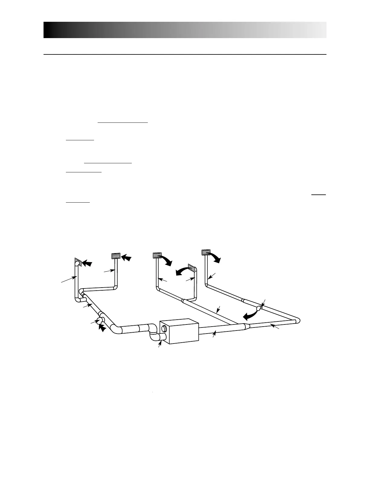
6.4.2 Example of a design for a fully ducted system for a unit having a high speed
performance of 222 cfm (See figure 9).
4” Ø
42 cfm
6” Ø
129 cfm
5” Ø
65 cfm
5” Ø
64 cfm
6” Ø
93 cfm
5”
6”
7”
7”
6”
6”
6”
4”
4”
4”
4”
7” Ø 222 cfm
7” Ø 222 cfm
4” Ø 42 cfm
6” Ø 84 cfm
6” Ø 96 cfm
6” Ø 138 cfm
figure 9