7
Screw nut and washer M10 to the anchor bolts, keeping the same
distance for all of them, in order to create a balanced support for
the ground plate.
Put anchor bolts M10 into holes, then tighten washers and bolts
M10 as shows Picture 10.
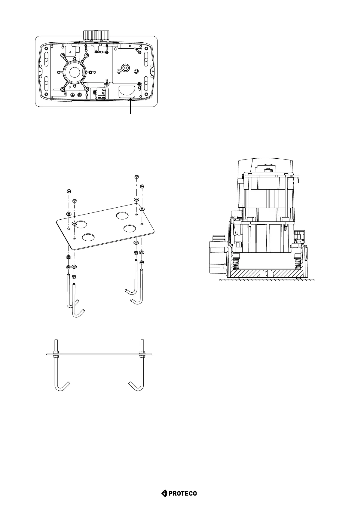
ELECTRIC
CABLES
SLOT
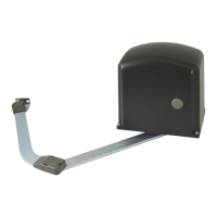
Picture 8: Gearmotor top view
Cast
the concrete and, before setting begins, put the ground plate
in the center, leaving a margin of 40/60mm; ground plate has to be
aligned to the gate and properly levelled.
Wait for the concrete to set completely.
ATTENTION: Keep the ground plate surface and anchor
bolts as clean as possible (screen the anchor bolts).
Leave electrical cables at least 30-50cm longer to allow easy
connection to the control unit.
MATRIX - rev. 1.1_09_2020
3.6 Fixing on ground
Loose washers and bolts M10 screwed on the ground plate.
Proceed to remove Matrix's cabinet.
Lay the gearmotor on the ground plate.
Match anchor bolts protruding from the ground plate to the aluminium
base slots.
Fix the gearmotor to ground plate using flat washers M10, Grower
washers and bolts M10 provided in the ttings bag.
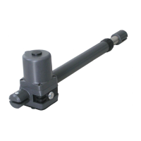
Pay attention while xing, cogwheel must be oriented towards the gate.
Attention! Drive electric cables through the aluminium base and
keep them away from components that may warm up (as motor,
transformer, etc etc).
Cut the membrane keeping an extra margin of 3 cm from ground
plate edge and t the cables for safety devices and power supply
connection.
Figura 11:
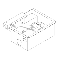
Picture 9:
Ground plate view
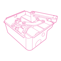
Picture 10: Anchor screws view
It is possible to adjust the heigth of the aluminium base calibrating
the 4 screws 10x50 and springs (this will be necessary only if Matrix
serves as replacement of a previous installation, refer to picture 11)
Heigth can be adjusted up to max. 19mm (without washer).
Unlock the gearmotor and set it to manual operation mode.
3.7 Manual operation
Switch the power off and release the gearmotor using the lock
barrel positioned on the alluminium base.
Lift the plastic tang to accede to the lock (Picture 12).
Plug the key in and turn it counter clockwise.
Pull the release lever completely to full opening (90°), (Picture 13).
Now you can move the gate manually.
ATTENTION: Be carefull, the gate may accidentally move.