20
EN
Requirements before the interconnection kit can be installed
• Electrical wiring must be done by a person with appropriate authorisation
• The boiler must be disconnected from power supply
• The boiler as well as the tank must be free of water
• Abide by the conditions detailed in this Guide, Installation and Operation Guide for Ray
electric boiler and for the B 120 S tank
Installation of hydraulic part
1. Remove the boiler front cover.
2. Install a shutting valve to the boiler heating
water outlet. Then install the mechanical part
of the actuator-controlled 3-way valve (Fig. 1,
position 3), so that the control valve is facing
right. Please note: shutting valve is not part
of the delivery.
3. To the 3-way outlet that is closer to the con-
trol valve – downstream actuator – connect
the heating system inlet pipe.
4. To the 3-way valve outlet that is further from
the control valve – downstream actuator
– connect a pipe leading to the tank heating
water inlet (see Operation Guide for B 120 S
tank). Install another shutting valve between
this pipe and the tank inlet.
5. To the boiler heating water inlet install a
filter, a shutting valve and then the distributor
which is part of the interconnection kit (Fig.
1, position 4). Please note: Filter and shutting
valve are not part of the interconnection kit.
6. To one of the distributor inlets connect the
heating system return pipe and to the other inlet connect the tank heating water return
pipe.
7. We recommend that you install on the tank heating water return a non-return flap valve
in the heating water flow direction. If you do this, you will prevent gravity circulation and
hence cooling of the tank. Install a shutting valve downstream the non-return flap valve.
8. Install a safety valve (6.3 bar) with a non-return flap valve to the tank hot water inlet.
9. To the hot water inlet and outlet install first shutting valves and then connect distribution
piping.
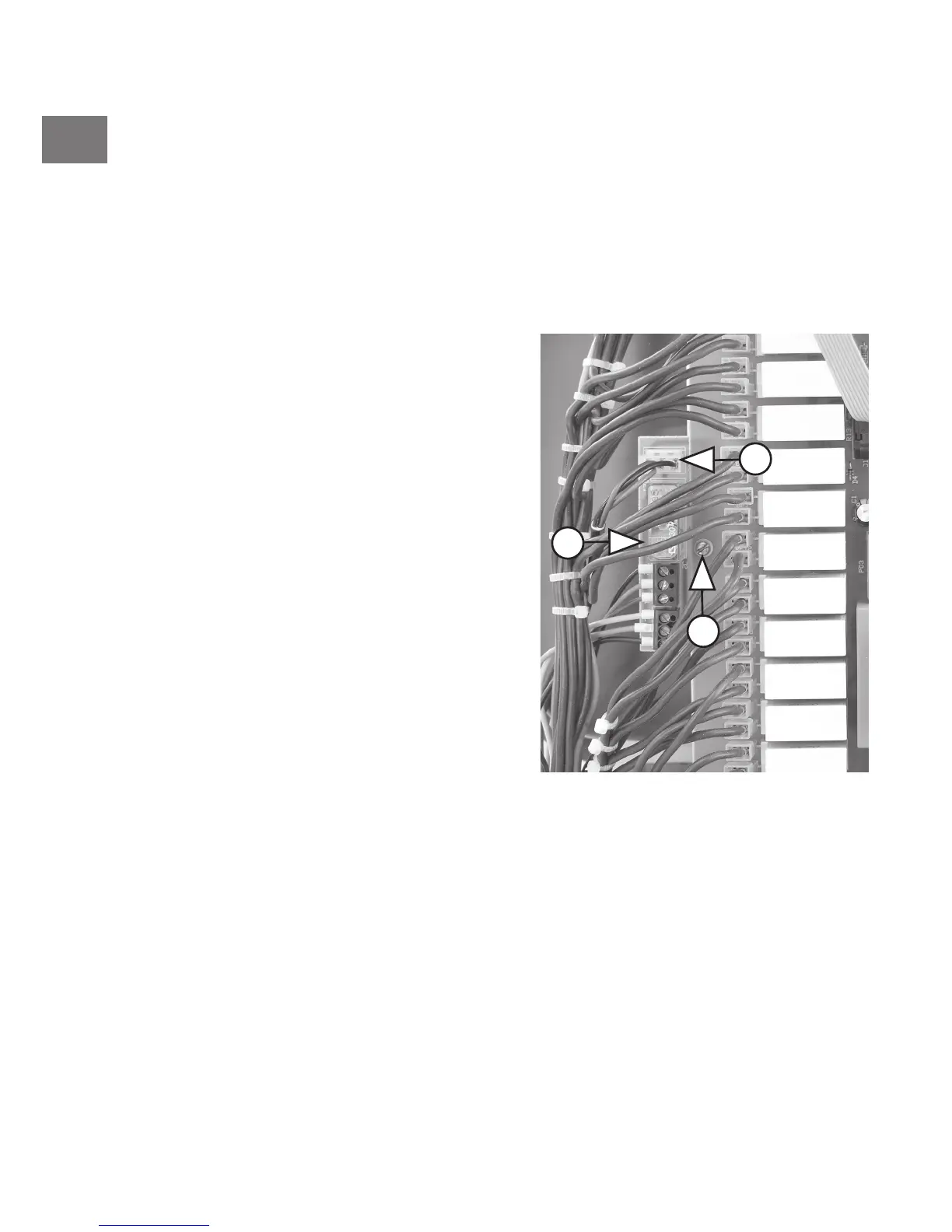
fig. 2
a
c
b