21
EN
Installation of electrical part
10. Release and partially unscrew the
boiler control board safety screw (Fig. 2,
position a).
11. Insert the control board of the actuator-
controlled 3-way valve (Fig. 2, position
b), and with the safety screw fasten it to
the boiler main control board.
12. Take out the cable with connectors from
the kit (Fig, 1, position 5), and plug the
larger of the connectors to the 3-way
valve actuator (Fig. 1. position 6).
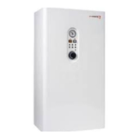
13. Take out the connector safety shield
from the kit (Fig. 1, position 10), and
thread the 3-way valve actuator cable
through the rectangular cut-out (Fig. 3)
14. Insert the safety shield circular cut-out
on the control part of the 3-way valve
actuator (see Fig. 3).
15. Insert the subassembly on the brass
part of the 3-way valve and secure
it with the clip which is part of the
interconnection kit (Fig. 1, position 7).
16. Insert the other end of the cable with the
smaller connector to one of the unused
cable glands from underneath the boiler
(you must select a cable gland), and
connect it to the newly installed control
board of the actuator-controlled 3-way
valve. (Fig. 2, position c).
17. Take out the cable harness form the interconnection kit (Fig. 1, position 2) and connect
the tank thermostat (Fig, 1, position 9) and the newly installed control board of the
actuator-controlled 3-way valve to the boiler connection terminal box.
18. Replace the boiler front cover.
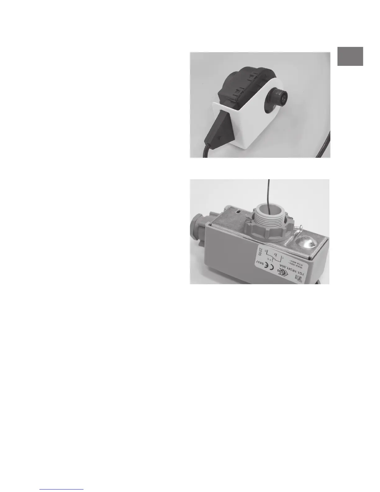
19. Insert the distance ring (Fig. 1, position 8) into the tank thermostat and secure it with a
self-cutting screw (Fig. 4).
20. Insert the thermostat capillary into the tank casing and push it in until it touches the
installed distance ring.
fig. 3
fig. 4