Page 86 of 126
Proton Products SL mini and SLR mini Series Speed and Length Gauges Instruction Manual - issue 1s
STANDARD ELECTRICAL INTERFACES
LOGIC INPUTS
Logic inputs connection
Two logic inputs are fitted as standard and may be accessed through the following pins:
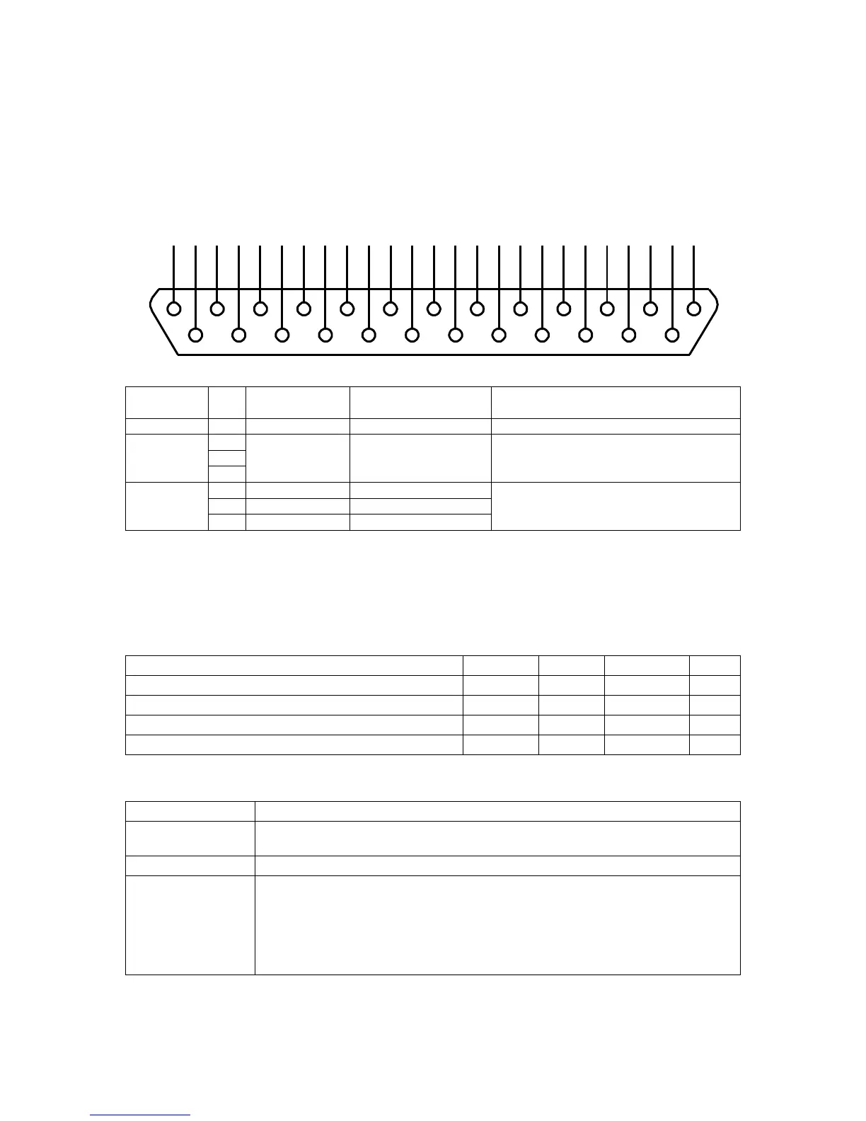
Connector type: DB25 female (socket)
Connect to cable and plug shields
Power supply and
signal ground (0V)
Low state (logic 0) voltage < +3V
High state (logic 1) voltage > +10.5V
Maximum input voltage ±30V
Logic inputs electrical specification
Logic inputs are NOT isolated from earth.
Inputs are internally pulled up to +15V via 8.2kΩ resistors; unconnected inputs default to the high
state.
Inputs will source a minimum current of 3mA when externally pulled down to the low state.
Low state (logic 0) input voltage
High state (logic 1) input voltage
Logic inputs can be connected to different types of signal sources as follows:
Mechanical or solid
state relay contact
Connect between logic input and DGND.
Connect the pull-down signal to the logic input and ground to DGND.
Connect an 820Ω resistor between the logic input and DGND to pull the
input down to 2.5V.
Connect the pull-up signal source to the logic input and ground to DGND.
For 24V signals (such as from a PLC), the power dissipation in the 820Ω
resistor can be reduced by connecting another 820Ω in series between the
pull-up signal source and logic input.
1
14
2
15
3
16
4
17
5
18
6
19
7
20
8
21
9
22
10
23
11
24
12
25
13
 Loading...