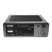
The device is the Proxxon CNC Control Unit CU 4, designed for controlling the stepper motors of CNC machine tools. It acts as an intermediary between a control computer running CNC software and the machine tool. The unit translates path information from the software into control commands for the stepper motors that drive the tool axes and also switches the spindle drives of the processing machine.
Function Description:
The CU 4 control unit enhances the capabilities of conventional, manually controlled processing machines by enabling CNC operation. It features four driver stages, allowing it to control up to four axes of a machine tool. These drives are connected to the control unit via Sub-D9 sockets on the rear, labeled for z, y, and x axes, with an additional 'U' socket for controlling instruments like positioning heads or dividing heads.
Communication with the control computer is established via a DB25 socket and a breakout board. The breakout board incorporates an optocoupler, providing electrical isolation between the control computer and the CU 4. This protects the control computer from potentially hazardous voltage spikes originating from the control unit.
The rear of the unit also includes two sockets (one mains plug and one Type F plug) that are wired in parallel and can be controlled by a relay. These sockets can be used to connect and control external devices such as the machine tool's drive, a cooling pump, or an extraction device, as needed by the CNC program.
Important Technical Specifications:
- Voltage Supply: 110-230 V (switchable), 50/60 Hz
- Power Input:
- Maximum total: 2700 Watt
- Power unit (internal): 200 Watt
- Sockets for connecting machinery: max. 2500 Watt
- Output Sockets: 2 units, 230 V, parallel, relay-switchable, max. 2500 W
- Power Amplifiers: 4 units, 48 V, 2A
- Compatibility: Suitable for stepper motors of NEMA sizes 17, 23, and 24, with 1600 steps/revolution.
- DB25 Socket Assignment (Control Computer Interface):
- Pin 2: Direction output x
- Pin 3: Clock output x
- Pin 4: Direction output y
- Pin 5: Clock output y
- Pin 6: Direction output z
- Pin 7: Clock output z
- Pin 8: Direction output U
- Pin 9: Clock output U
- Pin 11: Input limit switch U
- Pin 12: Input limit switch x
- Pin 13: Input limit switch y
- Pin 15: Input limit switch z
- Pin 17: Output 230 V relay
- All other pins are unassigned.
- Sub-D 9 Sockets Assignment (Stepper Motor Interface):
- Coil 1a, Coil 1b, Coil 2a, Coil 2b for motor windings.
- Limit Switch input.
Usage Features:
- Control Elements (Front Panel):
- Operating Display: Indicates the operational status of the unit.
- On-off Switch: For powering the unit on or off.
- Emergency Stop Switch: A prominent red button that, when pressed inward, immediately stops all slide movements and deactivates the spindle drive. It locks in place and must be released by turning it to the right before operations can resume.
- Connections (Rear Panel):
- Mains Cable: For power supply.
- Switched Power Sockets: Two sockets for connecting and controlling external machine tools or accessories (e.g., cooling pump, extraction device).
- DB25 Connection: For connecting to the control computer.
- Sub-D9 Connection Sockets (U, Z, Y, X): For connecting the stepper motor plugs of the machine tool axes.
- Safety Guidelines:
- Users must familiarize themselves with the potential hazards of the machine tool configuration and adhere to safety instructions from both the control unit and the machine tool manufacturer.
- The user is solely responsible for safe operation.
- Before operation, always check the integrity of the mains cable, other electrical cables, and the housing.
- Never open the housing of the control unit due to the risk of electric shock.
- Only operate the unit with the built-in mains cable, ensuring it's plugged into a grounded Type F socket.
- Ensure the electrical configuration of motors and wiring matches the specified values to prevent damage.
- Before any adjustment, maintenance, or tool changes on the machine tool, disconnect its plug from the CU 4's socket or engage the emergency stop to prevent accidental startup.
- Always maintain a safe distance from moving parts of the machine tool.
- Startup Procedure:
- Connect all cables (stepper motors, control computer) before connecting the mains cable to the CU 4.
- Ensure the on-off switch is in the "O" (off) position before connecting power.
- Do not switch on any electrical devices (computer, CU 4, machine) until all cable connections are complete.
Maintenance Features:
- Troubleshooting: A table is provided for common operational errors and their solutions:
- Green LED on front does not light up:
- Cause: Control unit not switched on. Solution: Turn on control unit.
- Cause: Voltage supply interrupted. Solution: Determine and eliminate the cause.
- Cause: Mains plug not plugged in correctly. Solution: Check and plug in correctly.
- Cause: Emergency stop switch is locked. Solution: Release emergency stop switch.
- Repair:
- The housing of the CU 4 must never be opened by the user.
- Repairs should only be carried out by qualified personnel.
- For repairs, the unit should be sent to the Proxxon Central Service division.
- Disposal:
- The device or its parts should not be disposed of with household waste.
- It contains valuable recyclable materials.
- Contact local disposal companies or municipal facilities for proper disposal information.
- EU Declaration of Conformity:
- The product complies with the essential safety and health requirements of the applicable EU Directives (EMC 2014/30/EU, Low Voltage 2014/35/EU, RoHS 2011/65/EU).
- Any unauthorized alterations to the system will void this declaration.