Marktronic User Guide 15-1
15. CIRCUMFERENTIAL FIXTURE
Introduction
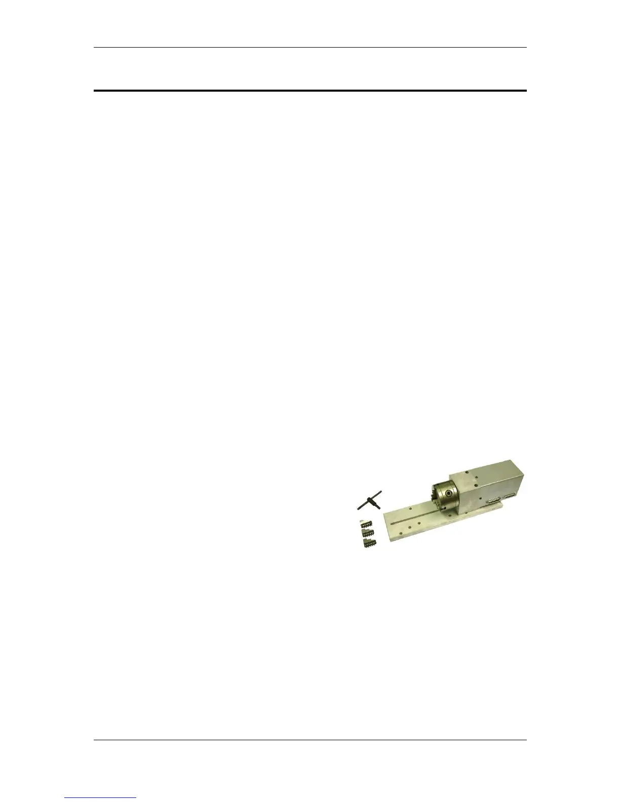
The circumferential fixture is used for marking around the diameter of the work
pieces which cannot be marked in the conventional way on the standard XYZ
arrangement.
Setting up the Circumferential Fixture
The fixture is supplied with 2 bolts or tee nuts with which to mount it to the
Marktronic base. It can be positioned with the top dead centre of the circumferential
fixture on the centre line of the Y-Axis marking areas. Eg. 100 x 100 marking area
centreline will be 50.0mm from home position of stylus or, 4" x 4" marking area will
be 2" from stylus home position. This setting can be adjusted by changing the Y
offset (F10, F3) to suit the position. Also ensure the marking head and any stylus
are not allowed to come into contact with the fixture. Damage will occur if this
happens.
Setting up the Controller
A 25 way to 25 way cable is provided to connect the controller to a circumferential
fixture. This cable is wired pin to pin and is identical to the head cable used between
the controller and the marking head. If a z axis and circ fixture is to be used, the Z
axis connects via the secondary port on the circ fixture, using a 25 way to 15way
cable. Ensure the cables are firmly connected and screwed in place. Never
disconnect the cables when the machine is powered up and operating, this could
damage the drive electronics.
Guide to effective marking
Unless the work piece is held firmly then there
is little hope of obtaining a good quality mark.
The Circumferential marking fixture is supplied
with a standard 3" 3 jaw chuck for general use.
This will not cover every size and shape of
work piece, but should cover a wide range of
work pieces. If the work piece/s you require
will not fit the 3 jaw chucks, special mandrels,
faceplates, tooling etc. can be provided for the
work piece/s in question. Information is given to enable the customer to make their
own mandrels, or if required the customer should contact the supplier of the
equipment .
The work piece should be supported at both ends whenever possible, especially if a
heavy mark is required.
To achieve holding work pieces that are more than 100 mm (4”) dia, the housing
fixture and roller support fixture may have to be raised.
IMPORTANT
When setting up the fixture, ensure the stylus, stylus nozzle and solenoid does not
make contact with any part of the fixture, chuck, mandrel or work piece.



 To Next Page