6
7.Valvemounting
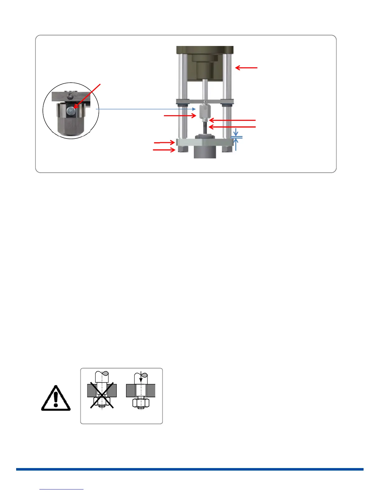
7.1Valvemountingspringextend(SE)
Initialposition:Valvestemisretracted
1. Putactuatorontothebracket.
2. Removethecouplingpinandscrewthecoupling13mmonthevalvestem.Theremustbea1mmgapbetween
thepillarsandthebracket.
3. Insertthecouplingpinagainandfixthelockingnut.
4. Connecttheactuatortoelectricsupply(see9.).
5. Retracttheactuatorspindlemanually(see10.7)untiltheedgesofthepillarsrestonthebracket.
6. Screwandtightenthepillarnuts.
7.2Valvemountingspringretract(SR)
Initialposition:Valvestemisextended
1. Putactuatorontothebracket,screwonandfixthepillarnuts.
2. Connecttheactuatortoelectricsupply(seechap ter9.).
3. Drivetheactuatormanually(seechapter10.7)untilthecouplingrestsonthevalvestem.
4. Removethespringclampwith
thecouplingpinandscrewthecoupling13mmonthevalvestem.
5. Redrivetheactuatormanually(seechapter10.7)untilthespringclampwiththecouplingpincanbere‐inserted.
RIGHT
WRONG
Beforethepillarnutsaretightened,makesurethatthepillars
aresittingonthevalvemountingbracket.Ifnecessary,correct
thepositionoftheactuatorbyusing manualoperation.Ifthese
instructionsarenotobserved,personalinjuryordamagetothe
actuatorand/orvalvemayresult.
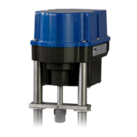
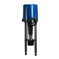
Figure4:Valvemounting
pillar
valve stem
locking nut
coupling
pillar nut
bracket
spring clamp with
coupling pin
1 mm