NORMI 13 (T42023)
Operating Manual - Constancy Test
D703.131.00/03 en 23
3.4.3 Optical Density
For both, automatic exposure control and man-
ual exposure setting, the measured optical den-
sity shall not deviate more than ±30% from the
reference value.
3.4.4 Luminance
For both, automatic exposure control and man-
ual exposure setting, the maximum deviation ΔL
of the measured luminance shall not exceed
+100% / -50%.
3.4.5 Pixel Value
Perform three ROI measurements for determining
the permitted deviations from the reference value:
– at the reference step (field in the middle, mea-
sured behind 1 mm of copper) P
reference
– at the adjoining step (measured behind
0.65 mm of copper) P
dose+step
– at the adjoining step (measured behind
1.4 mm of copper) P
dose+step
Calculate the maximum (P
+1
) and the minimum
(P
-1
) deviation from the reference value according
to the following formula:
– P
+1
= P
reference
+ factor × (P
dose+step
-P
reference
)
– P
-1
= P
reference
+ factor × (P
dose+step
-P
reference
)
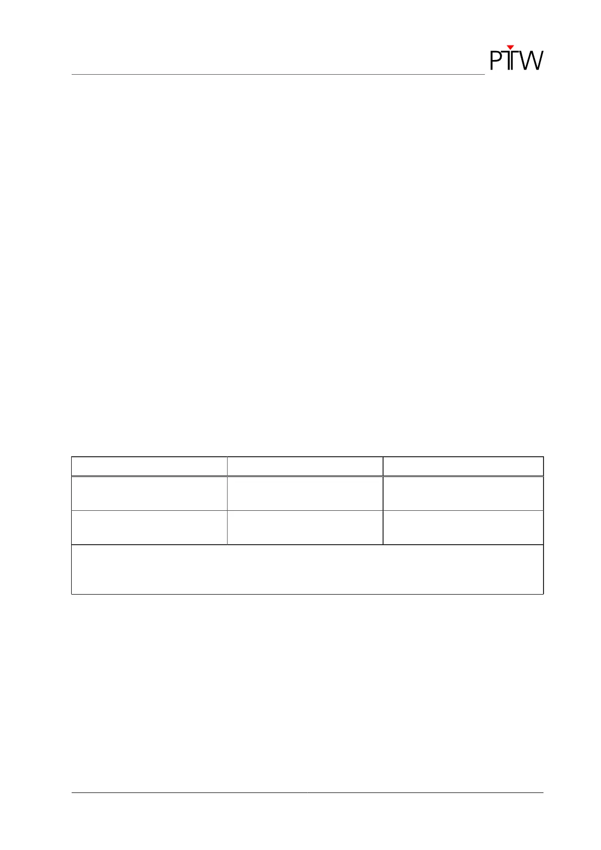
The factor used in the calculation depends on the
voltage, it is 0.45 for 70 kV and 0.7 for 100 kV (see
Table 1).
70 kV 100 kV
Limit of the pixel value towards a
lower dose: P
-1
P
1
+ 0.45 × (P
1.4
- P
1
) P
1
+ 0.7× (P
1.4
- P
1
)
Limit of the pixel value towards a
higher dose: P
+1
P
1
+ 0.45 × (P
0.65
- P
1
) P
1
+ 0.7× (P
0.65
- P
1
)
P
1
= pixel value behind the 1-mm Cu step (reference value)
P
0.65
= pixel value behind the 0.65-mm Cu step
P
1.4
= pixel value behind the 1.4-mm Cu step
Table 1: Formulas for calculation of the permitted deviations