Page 31 of 52
8.8 Hydraulic Bypass Valve (HBV)
All PulsaPro pumps incorporate a hydraulic bypass valve which is an adjustable spring-loaded
valve ported into the hydraulic cavity of the pump head. The valve is designed to protect the pump
against excessive hydraulic pressure and will not limit or regulate system pressure. The valve is
factory adjusted for pressure as originally specified, or at 10% above the rated pressure.
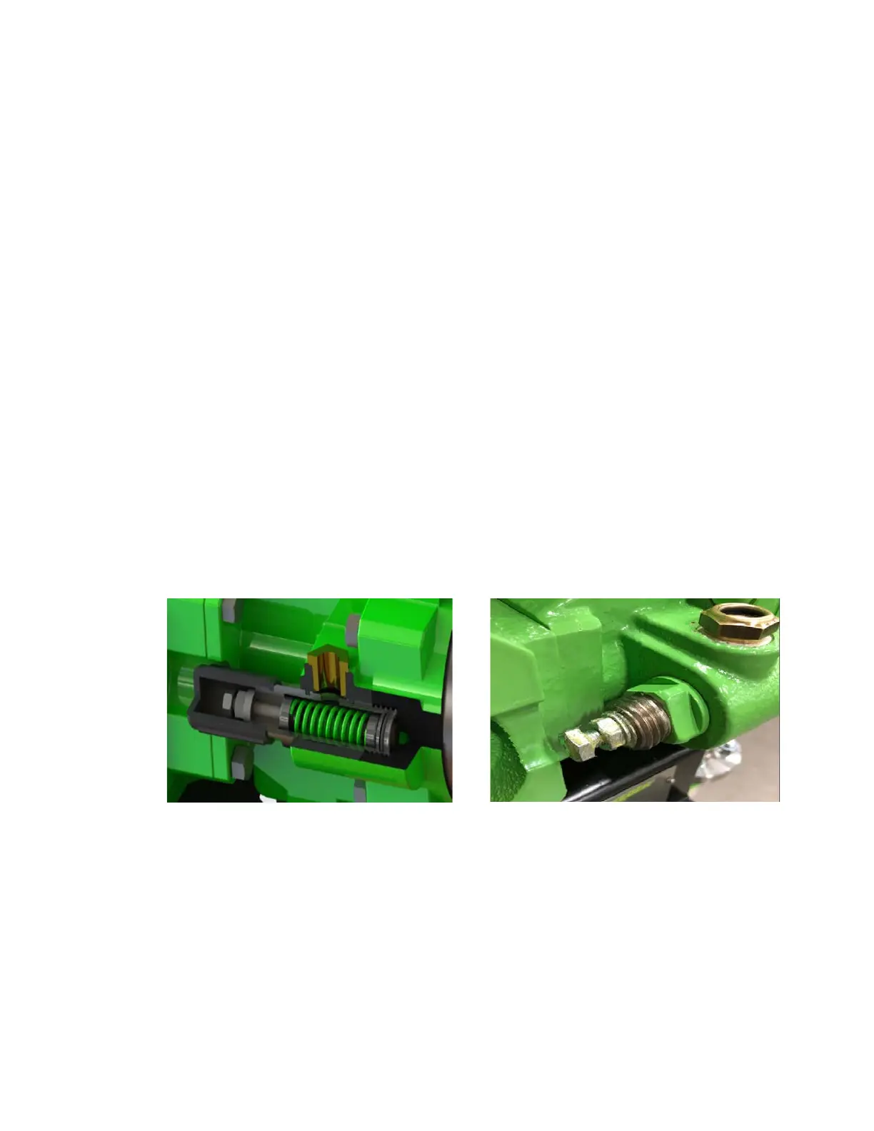
The HBV is located on the side of the pump head and any discharge, indicating over
pressurization, is visible through the diagnostic port via sight glass. If adjustments are necessary in
the field, remove the valve’s plastic cover and loosen the lock nut. When turning the adjustment
screw clockwise you will increase the bypass pressure, counterclockwise will decrease the bypass
pressure. The locking nut must be tightened after adjustment.
Pump damage may occur during a system upset, if the hydraulic bypass pressure is set higher
than 10% over the design pressure of the pump. Conversely, if the setting is too low the valve will
operate on each discharge stroke. This results in decreased pumping capacity and will eventually
affect the efficiency of the valve.
To check the hydraulic bypass pressure setting, install a pressure gauge and a regulating valve in
the pump discharge line. The gauge must be between the pump and valve. For convenience,
locate the two as close to the pump as possible. With the pump operating at maximum stroke
length, gradually increase the discharge pressure and observe when the HBV starts to operate.
The cracking pressure of the valve must be at least as high as the maximum pressure of the
system but no more than 10% over the pumps rated pressure.
Periodic inspection of the valve is recommended. If it becomes worn or damaged leakage will
occur.
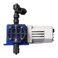
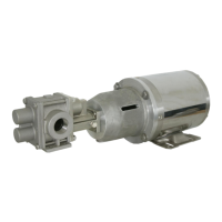
Figure 40 Figure 41
8.9 Push to Purge (PTP)
The PTP is a gravity operated ball check valve that automatically removes gases from the hydraulic
system. On each discharge stroke of the pump, hydraulic pressure drives the ball off the lower seat,
expelling any accumulation of gases at the top of the hydraulic system. An upper seat limits ball
travel and flow during each actuation. On each suction stroke, the ball is pre-positioned by gravity
against the lower seat to prevent reentry of gas into the system. When all gas has been expelled, a
small amount of oil will be displaced on each discharge stroke. This oil is returned by gravity to the
hydraulic reservoir.