QuickDraw
Storage and Semi-instantaneous
Boiler Water Heater
11 PV500-26 05/13
5.3 High Water Temperature Limit Control
The appliance is equipped with an adjustable temperature limit control and a non-adjustable high temperature limit
control. These controls are located inside the control cabinet and are accessed by removing the bottom cover.
The adjustable limit control is an auto reset type and should be adjusted at least 10 degrees above the set point of
the Operating Thermostat.
The high limit is an auto reset type with a fixed set point, but is optionally available as a manual reset type. If the high
limit is a manual reset type, it cannot be reset until the water temperature has dropped below its reset point.
5.4 Electronic Low Water Cut-Off (Optional)
When the water level is above the electrode position in the tank, the reset pushbutton will energize the control (LED
will be lit). The control remains energized until the water level recedes below the electrode position (LED will not be
lit). Unless otherwise specified, there is a three-second time delay on decreasing level. Water level must be below
tank probe location for full three seconds before control de-energizes.
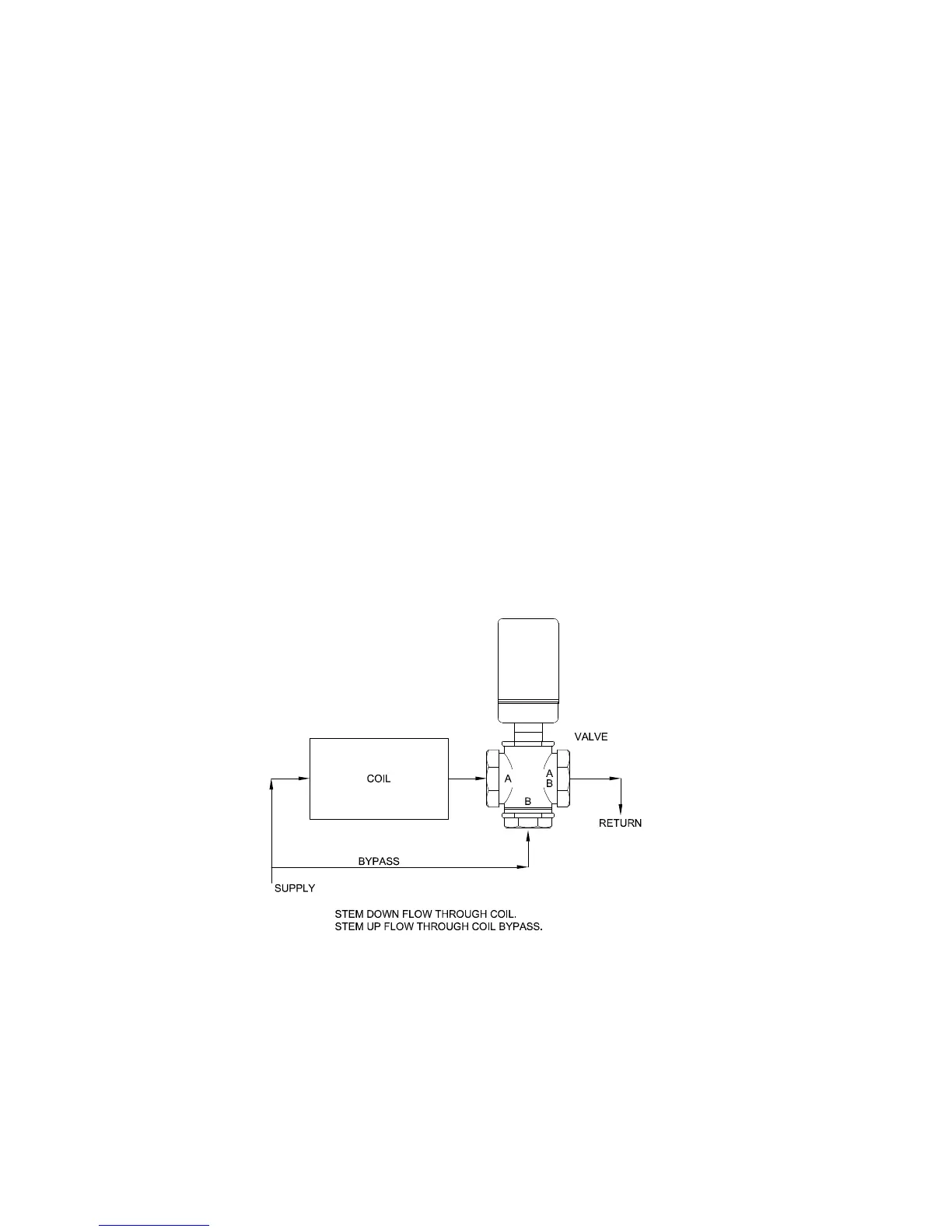
5.5 Sequence of Operation
(Refer to figure below)
1. When power is supplied through the unit’s On-Off switch, if the stored water temperature is below the operating
thermostat set point, the limit operating circuit closes creating a call-for-heat-demand, which energizes the
actuator on the three-way mixing valve.
2. The three-way mixing valve returns circulating boiler water to the boiler supply loop through its bypass ports. On a
call-for heat, the actuator motor runs and the actuator shaft extends causing the valve to divert the boiler water
through the heat exchanger before it is returned to the boiler supply loop.
3. When the demand is satisfied, the limit operating circuit opens and the valve actuator is de-energized. The
actuator motor stops running and the actuator shaft spring returns to the retracted position causing the boiler
water to divert through the bypass ports and return to the boiler water supply loop.