fluorescent
lamp
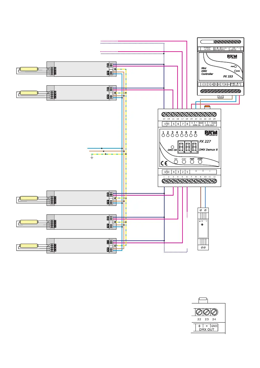
4. CONNECTION DIAGRAM
1-10 V electronic ballast
Examples of connection:
5. DMX SIGNAL CONNECTION
PX227 must be connected to DMX line in series. This means
that DMX IN terminals in the device must be provided with the
driving cable, and then from DMX OUT connector the driving
cable must be provided to other DMX receivers.
If PX227 is the last device in DMX line, "DMX+" and "DMX-”
terminals must be provided with the terminator – resistor of 120
Ohm between pins 22 and 23.
120 Ohm
5
power supply
12-24 V DC
L
N
DC OK
230 V AC
50 Hz
L
N
terminator
12-24V DC
V+
Electronic Ballast
DC 1-10V
AC 230V
V+
Electronic Ballast
DC 1-10V
AC 230V
V+
Electronic Ballast
DC 1-10V
AC 230V
V+
Electronic Ballast
DC 1-10V
AC 230V
V+
Electronic Ballast
DC 1-10V
AC 230V
to next
fluorescent lamp
to next fluorescent lamp
to next fluorescent lamp
DMX controller e.g.
PX333
fluorescent
lamp
fluorescent
lamp
fluorescent
lamp
fluorescent
lamp
1-10 V electronic ballast
 Loading...