ww w.PyleUSA.com
8
DIAGRAM 3: POWER MODE SELECTION
SYSTEM DESIGN EXAMPLES
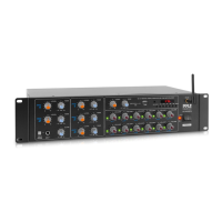
There are many ways to congure the PT8000CH amplier. The following pages
contain some typical installation examples. Use these examples to generate
ideas for your system design.
Multi-Room Installation Example (Diagram 4)
This illustrates the simplest use of the PT8000CH, distributing audio throughout
the home. In this example only one source can be selected at a time, all pairs of
speakers have the same audio signal available. The Input Selection switch is set to
“BUS” on all channels. Adjacent channels are assigned left and right.
Multi-Zone Example #1 (Diagram 5)
This illustrates the simplest way to provide an audio signal to one area that is
independent of the main audio signal. Zone 2 uses a CD player connected to
just that Zone. The rest of the system operates Zone 1 and is connected to
the preamplier/receiver. The Input Selection switch on channels 1-10 is set to
“BUS” with adjacent channels assigned left and right. The Input Selection Switch
on channels 11 and 12 are set to “LINE”.
Multi-Zone Example #2 (Diagram 6)
This illustrates the ability to listen to dierent audio signals in each zone, indepen-
dent of every other zone. The system relies on a multi-zone preamplier
or up to 6 independent preampliers.
The Input Selection switch on each channel is set to “LINE”
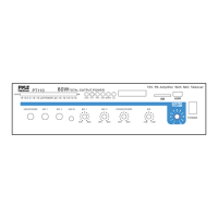
12-15V AC/DC
TRIGGER INPUT
12-15V AC/DC
TRIGGER INPUT
12V CONTROL
OUTPUT
AUDIO SENSE CONSTANT
2.1mm x 5.5mm
Power Input Jack
Mode Switch 3.5mm Power
Output Jack