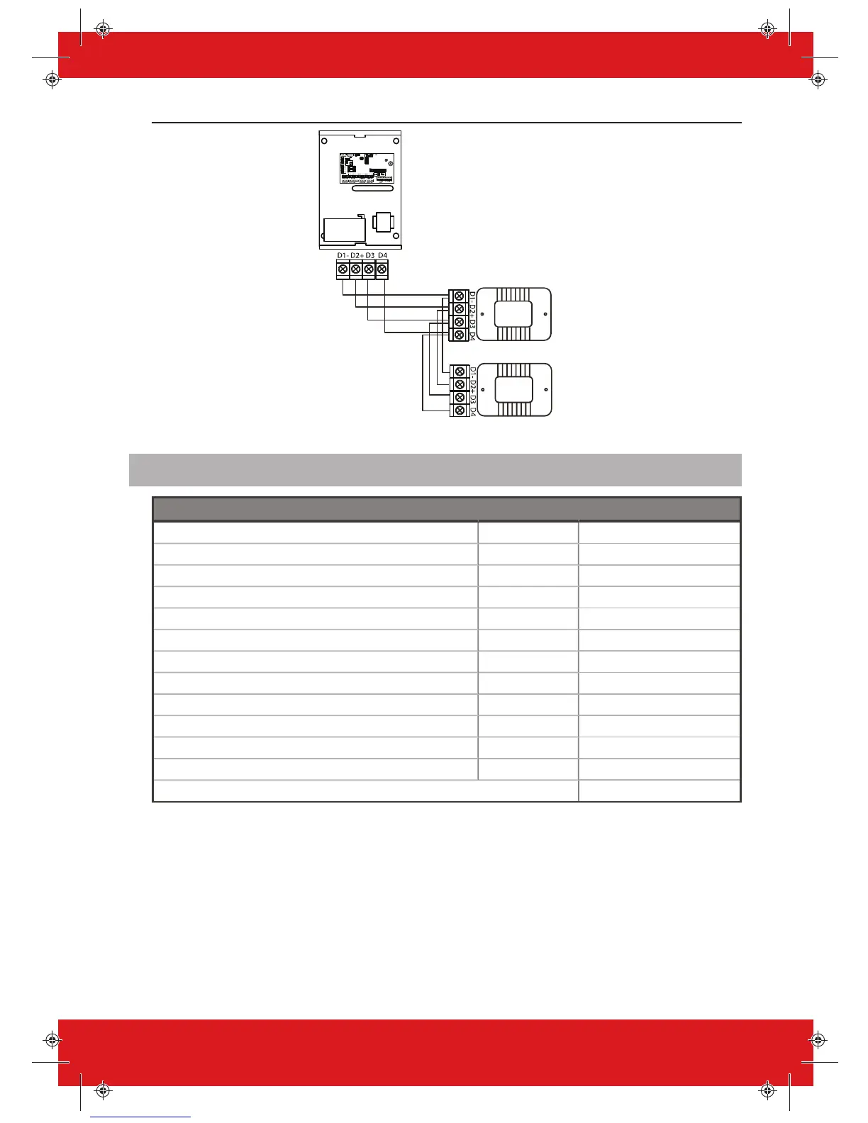
Figure 3: Daisy Chain Wiring example
Input Mapping Overview
Devices Address Available inputs
PCX PCB N/A 1-8
RIX-8I / RIX8+PSU / RIX32-WE (Device A) 0 9-16
RIX-8I / RIX8+PSU / RIX32-WE (Device A) 1 17-24
RIX-8I / RIX8+PSU / RIX32-WE (Device A) 2 25-32
RIX-8I / RIX8+PSU / RIX32-WE (Device A) 3 33-40
RIX-8I / RIX8+PSU / RIX32-WE (Device B) 4 41-48
RIX-8I / RIX8+PSU / RIX32-WE (Device B) 5 49-56
RIX-8I / RIX8+PSU / RIX32-WE (Device B) 6 57-64
RIX-8I / RIX8+PSU / RIX32-WE (Device B) 7 65-72
PCX-LCDP 0 73-74
PCX-LCDP / PROX-I / PROX-E 1 75-76
PCX-LCDP / PROX-I / PROX-E 2 77-78
Total 78
2 x PCX-RIX32-WE can be connected to the PCX. Each expander allows 32 inputs which are
separated into 4 addresses (each address enables 8 wireless inputs). It is possible to mix the wired
and wireless remote expanders.
14 PCX Installation Guide 102017852 - V01