Page 20
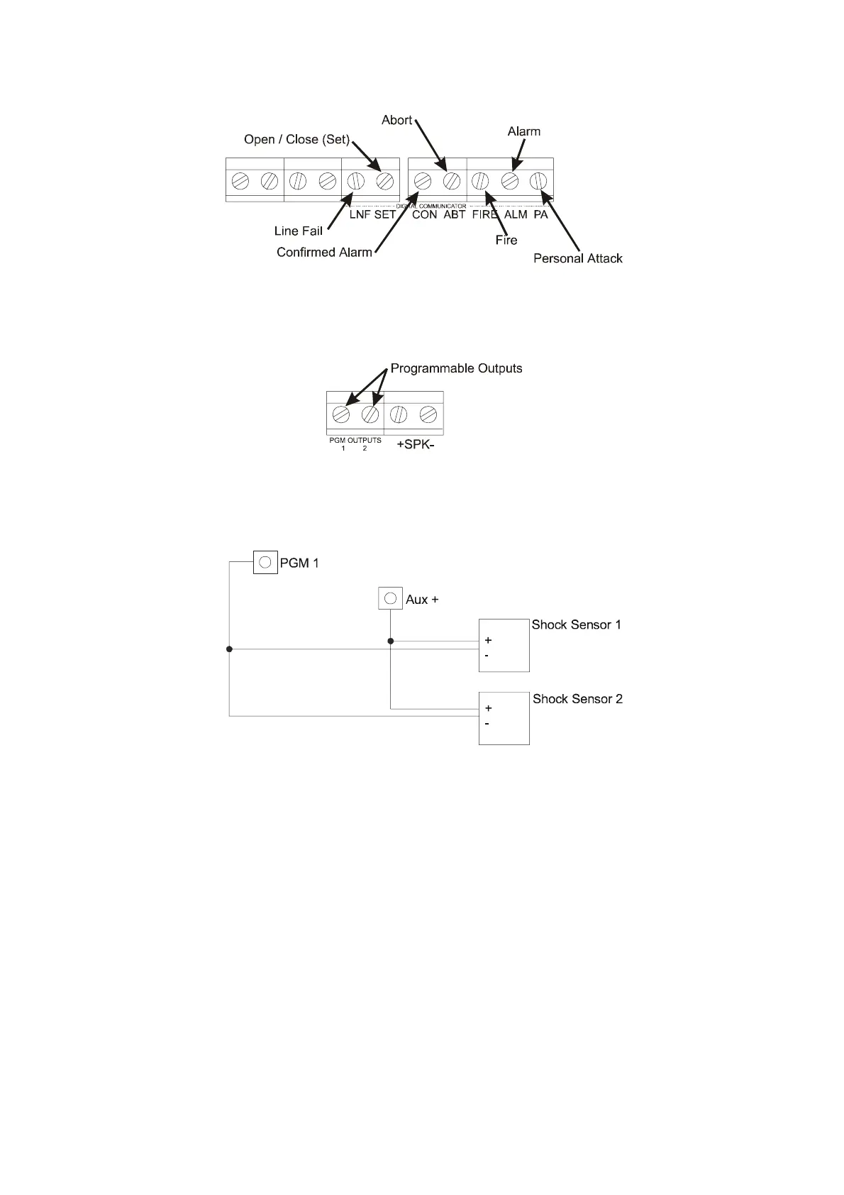
8.10 Digital Communicators
The Digital Communicators can be programmed to switch between 0 to 12V or 12 to 0V except the line fail
which is factory set for input to 0V.
8.11 Programmable Outputs
There are two programmable Outputs which are switched negative (-) to positive (+) or positive (+) to
negative (-) depending upon which System Option is programmed.
8.12 Shock Sensors
Up to 20 shock sensors wired in parallel, may be used with the Sterling10 panel. Only PGM 1 can be used for shock
sensor reset.
NOTE: Do Not use Programmable Output 2 for the shock sensors. If Programmable Output 2 is used, the
shock sensors will not reset after an alarm activation.
 Loading...