Rins136 Issue 9 Page 27
Enter for final door.
9.20 Set D Set Option
Enter
Enter
for timed exit,
Enter for push to set or
Enter for final door.
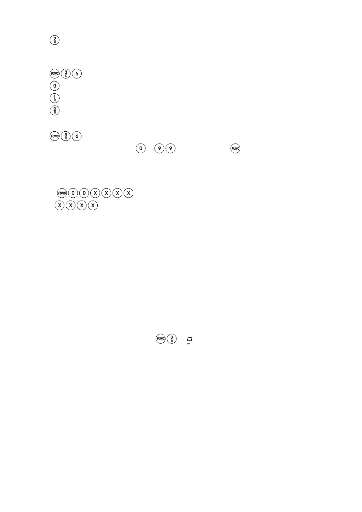
9.21 Final Door
Enter
followed by the time required in seconds (
to seconds) followed by .
Incorrect entry gives an audible error tone and correct entry gives three bleeps. Final door delay is factory set to seven
seconds. If the exit door is reopened the delay is reset and the countdown commences when the exit door is finally
closed.
9.22 Exiting Engineer Mode
Enter
(Where
is the 4 digit Engineer Code).
Refer to the User Instructions for using the Sterling after programming.
10 LED FUNCTION
Panel PCB
Supply LED on : Indicates AC supply
Remote Keypad
Supply LED on : Indicates AC supply and / or battery supply
11 SYSTEM FAULTS
There are 4 fault conditions automatically detected by the Sterling 10. The user is informed of a fault via the fault LED.
The LED will illuminate and an error tone will be emitted every 5 seconds when the panel is in day mode, press the
function key to stop the error tone. The fault LED will remain on until the fault has been corrected.
To determine the fault go into the log by entering
. A symbol followed by 1 - 4 will be displayed.
1 Bell Fuse Failure
2 Auxiliary Fuse Failure
3 Telephone Line Failure
4 Mains (AC) Failure
 Loading...