© 2011 Directed Electronics. All rights Reserved. 1
Quick Reference Install Guide
Security and Remote Start
Responder LE
CPU1
10A FUSE
MINI ATM
RPN: 8540
LIGHT FLASH POLARITY
(10A (MAXIMUM) FUSE JUMPER)
+ -
Optional Mux Port
(for additional sensors)
Bitwriter
Port
Neutral Safety
Switch
1
10 9 8 7 6
12345
1
1 8
51
1 3
10
12
18
10
9
1
1 12
D2D Port (for external
Xpresskit interface module)
10A FUSE
MINI ATM
RPN: 8540
LIGHT FLASH POLARITY
(10A (MAXIMUM) FUSE JUMPER)
+ -
ON
IMPORTANT! Neutral Safety
switch must be plugged in
and in the ON position
D2D jumpers; Factory setting is horizontal position.
Most Xpresskit modules use this setting, check the
Xpresskit installation guide for the specific setting.
Temperature
Sensor
RF Port
for IVU
Control Center
10A FUSE
MINI ATM
RPN: 8540
LIGHT FLASH POLARITY
(10A (MAXIMUM) FUSE JUMPER)
+ -
09
11
10
06
08
07
22
66
88
77
1
1
1
1
0
1
1
1
1
0
99
55
1
2
1
2
44
33
ELECTRONICS
R
3
1
4
2
TACH LEARN THREASHOLD
JMP1 OFF ON
CPU1
NOTE: Pin 1 is on the left
TACH threshold OFF:
TACH threshold ON:
Bitwriter
Port
Neutral Safety
Switch
Remote
Start In
Status
LED
Valet
Port
Door Lock/
Unlock Output
Relay Out
Port
H2
Port
10 9 8 7 6
12345
1
1 8
51
1 3
10
To change
jumper
settings
1 12
10A FUSE
MINI ATM
RPN: 8540
LIGHT FLASH POLARITY
(10A (MAXIMUM) FUSE JUMPER)
+ -
09
11
10
06
08
07
22
66
88
77
1
1
1
1
0
1
1
1
1
0
99
55
1
2
1
2
44
33
ELECTRONICS
R
3
1
4
2
TACH LEARN THREASHOLD
JMP1 OFF ON
CPU1
NOTE: Pin 1 is on the left
TACH threshold OFF:
TACH threshold ON:
Bitwriter
Port
Neutral Safety
Switch
Remote
Start In
Status
LED
Valet
Port
Door Lock/
Unlock Output
Relay Out
Port
H2
Port
1
1
1 8
51
1 3
10
12
To change
jumper
settings
1 12
New Features
• EnhancedTachFiltering
• AdditionofAux4foratotalof5ChannelOutputs
• New18pinHarness
• ImprovedcurrentcapableAux&OEMAlarmOutputs
• EnhancedTemperatureReading
10A FUSE
MINI ATM
RPN: 8540
LIGHT FLASH POLARITY
(10A (MAXIMUM) FUSE JUMPER)
+ -
09
11
10
06
08
07
22
66
88
77
1
1
1
1
0
1
1
1
1
0
99
55
1
2
1
2
44
33
ELECTRONICS
R
3
1
4
2
TACH LEARN THREASHOLD
JMP1 OFF ON
CPU1
NOTE: Pin 1 is on the left
TACH threshold OFF:
TACH threshold ON:
Bitwriter
Port
Neutral Safety
Switch
Remote
Start In
Status
LED
Valet
Port
Door Lock/
Unlock Output
Relay Out
Port
H2
Port
1
10 9 8 7 6
12345
1
1 8
51
10
12
To change
jumper
settings
1 12
CPU1
10A FUSE
MINI ATM
RPN: 8540
LIGHT FLASH POLARITY
(10A (MAXIMUM) FUSE JUMPER)
+ -
Bitwriter
Port
Neutral Safety
Switch
Status
LED
Valet
Port
1
10 9 8 7 6
12345
1
1 8
51
1 3
10
12
TACH threshold OFF:
TACH threshold ON:
To change
jumper settings
1 12
D2D Port
(for external
Xpresskit
interface
module)
Optional Mux Port
(for additional sensors)
10A FUSE
MINI ATM
RPN: 8540
LIGHT FLASH POLARITY
(10A (MAXIMUM) FUSE JUMPER)
+ -
ON
IMPORTANT! Neutral Safety
switch must be plugged in
and in the ON position
D2D jumpers; Factory setting is horizontal position.
Most Xpresskit modules use this setting, check the
Xpresskit installation guide for the specific setting.
RF Port
for IVU
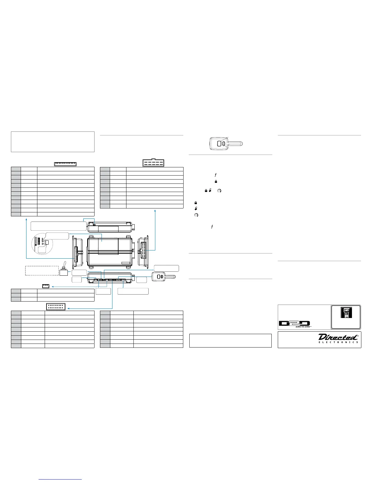
Wiring Connections
Main Harness (H1), 12-pin connector
H1/1
RED/WHITE (-) 200mA TRUNK RELEASE OUTPUT
H1/2
RED (+)12VDC CONSTANT INPUT
H1/3
BROWN (+) SIREN OUTPUT
H1/4
WHITE/BROWN PARKING LIGHT ISOLATION WIRE - PIN 87a of onboard relay
H1/5
BLACK (-) CHASSIS GROUND
H1/6
VIOLET (+) DOOR TRIGGER INPUT
H1/7
BLUE (-) TRUNK PIN/ INSTANT TRIGGER INPUT (N/C OR N/O)
H1/8
GREEN (-) DOOR TRIGGER INPUT (N/C OR N/O)
H1/9
BLACK/WHITE (-) 200mA DOME LIGHT SUPERVISION OUTPUT
H1/10
WHITE/BLUE (-) REMOTE START/ TURBO TIMER ACTIVATION INPUT
H1/11
WHITE PARKING LIGHT OUTPUT
H1/12
ORANGE (-) 500mA GROUND WHEN ARMED OUTPUT
Remote Start, (H3) 10-pin connector
H3/1
PINK (+) IGNITION 1 INPUT/OUTPUT
H3/2
RED/WHITE (+) FUSED (30A) IGNITION 2 / FLEX RELAY INPUT 87
H3/3
ORANGE (+) ACCESSORY OUTPUT
H3/4
VIOLET (+) STARTER OUTPUT (CAR SIDE OF THE STARTER KILL)
H3/5
GREEN (+) STARTER INPUT (KEY SIDE OF THE STARTER KILL)
H3/6
RED (+) FUSED (30A) IGNITION 1 INPUT
H3/7
PINK/WHITE (+) IGNITION 2 / FLEX RELAY OUTPUT
H3/8
PINK/BLACK (+) FLEX RELAY INPUT 87A key side (if required) of FLEX RELAY
H3/9
RED/BLACK (+) FUSED (30A) ACCESSORY/STARTER INPUT
H3/10
NC No Connection
Door Lock, 3-pin connector
1
BLUE (-) 500 mA UNLOCK OUTPUT
2
EMPTY NOT USED
3
GREEN (-) 500 mA LOCK OUTPUT
H2 Harness, 18-pin connector
H2/1
LIGHT GREEN/BLACK (-) 200mA OEM ALARM DISARM OUTPUT
H2/2
ORANGE/BLACK (-) 200mA AUX 4 OUTPUT
H2/3
GREEN/WHITE (-) 200mA OEM ALARM ARM OUTPUT
H2/4
VIOLET/BLACK (-) 200mA AUX 2 OUTPUT
H2/5
WHITE/BLACK (-) 200mA AUX 3 OUTPUT
H2/6
WHITE/VIOLET (-) 200mA AUX 1 OUTPUT
H2/7
GREY/BLACK (-) DIESEL WAIT TO START INPUT
H2/8
BROWN/BLACK (-) 200mA HORN HONK OUTPUT
H2/9
VIOLET/WHITE TACHOMETER INPUT
H2/10
DARK BLUE (-) 200mA STATUS OUTPUT
H2/11
PINK/WHITE (-) 200mA FLEX RELAY CONTROL OUTPUT
H2/12
ORANGE (-) 200mA ACCESSORY OUTPUT
H2/13
PURPLE (-) 200mA STARTER OUTPUT
H2/14
PINK (-) 200mA IGNITION 1 OUTPUT
H2/15
GREY (-) HOOD PIN INPUT (N/C OR N/O)
H2/16
BLUE/WHITE (-) 200mA 2ND STATUS /REAR DEFOGGER OUTPUT
H2/17
BROWN (+) BRAKE SHUTDOWN INPUT
H2/18
BLACK/WHITE (-) NEUTRAL SAFETY INPUT
Bitwriterswithadatecodeof6aorolderrequireanIC
upgrade(p/n998M).Somebitwriterswithadatecode
of6Bdo not requiretheICupgrade,refertotechtip#
1112formoreinformation.
The Bitwriter® (p/n 998U)
requires chip version 2.7 or
newertoprogramthisunit.
Installation Points
Control Center
Control Center
Control
Center
Control Center
Valet switch
LED
Control button
Status LED
Control Center
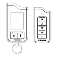
Adjusting the Stinger Double-Guard Shock Sensor
Important!Makesurethekeypadisunlockedandthevehicleisdisarmedwithno
openzones.TheonboardshocksensorcanbeadjustedusingtheLEremote.
Adjusting the sensor:
1. Disarmthesystem,turntheignitionOffandcloseallthedoors.
2. Pressandholdthe
buttonoftheremotecontrolfor8secondsoruntilthe
amberLEDturnsonandyouhearonelongbeep.
3. Pressandholdthe
button1.5secondsoruntiltheamberledcomeson
solid.-Thecontrolmoduleemitsonelongchirp,conrmingthatithasentered
adjustmentmode.
4. Pressthe
buttonstoadjustthesensorlevel.
Note:You cantest thenewsetting bycautiously impactingthe vehiclewith
increasingintensityuntilthesirenchirps,indicatingtheimpactlevelrequiredto
fullytriggerthealarm.
•
button: Pressing this button increases the sensitivity one level. The siren
chirpstwiceconrmingthesensitivityadjustment.
•
button: Pressingthis button decreasesthe sensitivityone level. Thesiren
chirpsonceconrmingthesensitivityadjustment.
•
button:Pressingthisbuttonresetstodefaultlevel7.Thesirenchirpsthree
times.
To exit the shock sensor adjustment mode from the remote control:
Pressandreleasethe
buttonanytimeduringprogrammingtogobacktothe
main menu. Press and hold for 1.5 seconds in the main menu to exit program-
ming.
To exit the shock sensor adjustment mode from the control module:
Openanentrypointorturnontheignition,thecontrolmoduleemitsonelong
chirpexitingadjustmentmode.
Learning the Tach (not needed with Virtual Tach)
To learn the tach signal:
1. Startthevehiclewiththekey.
2. Within5seconds,pressandholdtheControlbutton.
3. After3secondsthestatusLEDonyourControlCenterlightsconstantwhen
thetachsignalislearned.
4. ReleasetheControlbutton.
Initializing Virtual Tach (not needed with hardwire tach inputs)
To program Virtual Tach:
1. Afterthe install is complete,remote startthe engine. The programmingop-
erationmayrequire3cranksofthestarterbeforetheenginestartsandruns.
Donot turnoff theremote start ifthis happens,it isa normalprogramming
operation.
2. Oncetheenginebeginsrunning,letitrunforatleast30seconds.
3. Using theRemote, send the Remote start command to turn remote start off.
VirtualTachisprogrammed.
ToresetVirtualTach,gointotheRemotePairingsectionofthisguideandpress/re-
leasetheControlbutton4timesforstep#4,thenpressandholdtheControlbutton
toresetVirtualTach.VirtualTachcannotberesetwiththeBitwriter.
Note:
VirtualTachcannotbeusedinMTSManualTransmissionMode.Itisalsonot
recommendedfordieseltrucks.
VirtualTachhandlesdisengagingthestartermotorduringremotestarting–itdoes
notaddressover-rev.Ifthecustomerwantstohavetheover-revprotectioncapability,
thetachwiremustbeconnected.
Important:Aftersuccessfully learningVirtualTach,asmall minorityofve-
hiclestartersmayover crankorundercrankduring remotestart.TheBit-
writercanbeusednetunethestarteroutputtimein50mSincrementsto
compensateforsuchanoccurrence.
Remote Start Shutdown/Startup Diagnostics
To perform shutdown diagnostics:
1. WiththeignitionOff,pressandholdtheControlbutton(onControlCenter).
2. TurntheignitionOnandthenbackOffwhileholdingtheControlbutton.
3. ReleasetheControlbutton.
4. PressandreleasetheControlbutton.ThestatusLEDashestoreportthelast
shutdownforoneminuteoruntiltheignitionisturnedon,asshowninthe
followingtable:
Status LED Flashes Shutdown Mode
1ash Runtimeexpired
2ashes Over-revshutdown
3ashes LowornoRPM
4ashes Transmittershutdown(oroptionalpushbutton)
5ashes (+)Brakeshutdown
6ashes (-)Hoodshutdown
7ashes Timermode/Turbomode/Manualmodeerror*
8ashes Neutralsafetyshutdown
9ashes Lowbattery(voltagemode)
10ashes Alarmtriggered**
11ashes Wait-to-startinputtimedout
* Timermodeerror: Ignitionisonorshutdowninput isactivewhenactivating
timermode.
Turbomodeerror: Turbomodeisprogrammed off,engineis notonorshut-
downinputisactive.
Manualmodeerror:MTSmodenotenabled.
** Alarmwastriggeredduringremotestartsequence.
Startup Diagnostics:Ifthevehiclefailstoactivatetheremotestart,theremotestart
modulewillnotifyyouviayourResponderLEremotecontrolandwillashthepark-
inglightsonthevehicletonotifyyouofwhatcausedtheno-startsituation.
Parking Light Flashes
5ashes Brakewireisactive
6ashes Hoodpinwireisactive
7ashes Manualtransmissionmodeisenabledandnotinitialized.
8ashes Neutralsafetywirehasnogroundortheneutralsafety
switchisOff.
Long Term Event History
Thesystemstoresthelasttwofulltriggersinmemory.Thesearenoterasable.Each
timetheunitseesafulltrigger,theolderofthetwotriggersinmemoryisreplacedby
thenewtrigger.Toaccesslongtermeventhistory:
1. WiththeignitionOff,pressandholdtheControlbutton(onControlCenter).
2. TurntheignitionOn.
3. ReleasetheControlbutton.
4. Within5seconds,pressandreleasetheControlbutton.ThestatusLEDashes
ingroupsindicatingthelasttwozonesthattriggeredtheunitfor1minuteor
untiltheignitionisturnedoff.Refertotableofzones(overleafonpage2).
Note:TheWarnAwaytriggersarenotstoredtomemoryandisnotreported.
SeefullInstallationGuideformore
detailedinformationonthissystem.
Suchinformationandmorecanbe
foundonlineat:
www.directechs.com
Logo, Directed Electronics w-driven.eps
Logo, Directed with designed in USA.eps
Logo, Directed with Distributed By.eps
Directed Logo Usage