10
Only install clamp systems approved by Q.CELLS. Failure to do so will void the warranty. The
list is available on www.q-cells.com.
Upon request, Q.CELLS can test clamp systems for approved use.
GENERAL REQUIREMENTS FOR FASTENING THE CLAMP SYSTEM:
• Ensure that the threaded connections do not generate extra stress on the module. The
modules must be positioned “oating”.
• Don’t attach the metal clamps directly to the glass. Use a suitable, silicone-free rubber
support between the module and the substructure or clamps.
• Adjust the clamp height to the module thickness.
• Ensure that the clamps have a width of
≥ 100 mm.
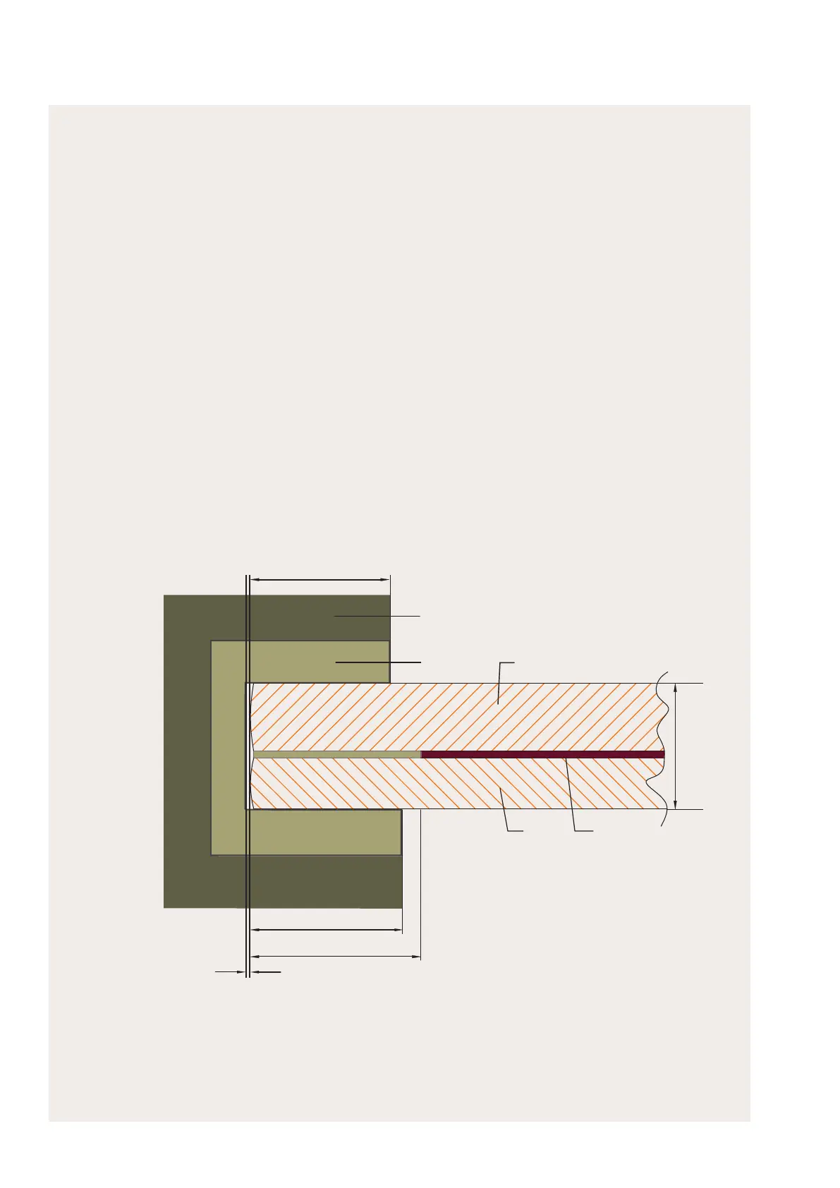
• Ensure that the clamps do not throw shadows onto the active cells. The distance from the
glass edge to the rst active cell is 18.5 mm (Figure 3).
• Ensure that clamps overlap the glass edge (Figure 3):
· 10 mm to 15 mm on the top side of the module
· 12 - 16 mm on the module back side
These specications also apply for the support of support longitudinal.
• Ensure a minimum gap of > 1 mm between the glass edge and inner side of the clamp at
25 °C (Figure 3) to allow for thermal expansion of the module.
• Lock the clamp into position by fastening the screw to the material-dened limit-point.
CLAMP SYSTEMS
5.2 MECHANICAL ASSEMBLY - UNFRAMED MODULES
INSTALLATION AND OPERATION MANUAL FOR CIGS SOLAR MODULES Q-CELLS SE - EUROPE
FIGURE 3: Clamp overlap of glass edge on the module top side (10-15 mm) and module back side (12 - 16 mm),
distance between glass edge and inner side of clamps (> 1 mm)
1 Clamp (schematic)
2 Rubber
3 Glass (module top side)
4 Glass (module underside)
5 Active area
10–15
12 - 16
16.5
7.3 ± 0.5
> 1
2
1
3
4
5
 Loading...