4
INSTALLATION AND OPERATION MANUAL FOR CIGS SOLAR MODULES Q-CELLS SE - EUROPE - EUROPE
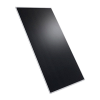
2 PRODUCT DESCRIPTION Q.SMART
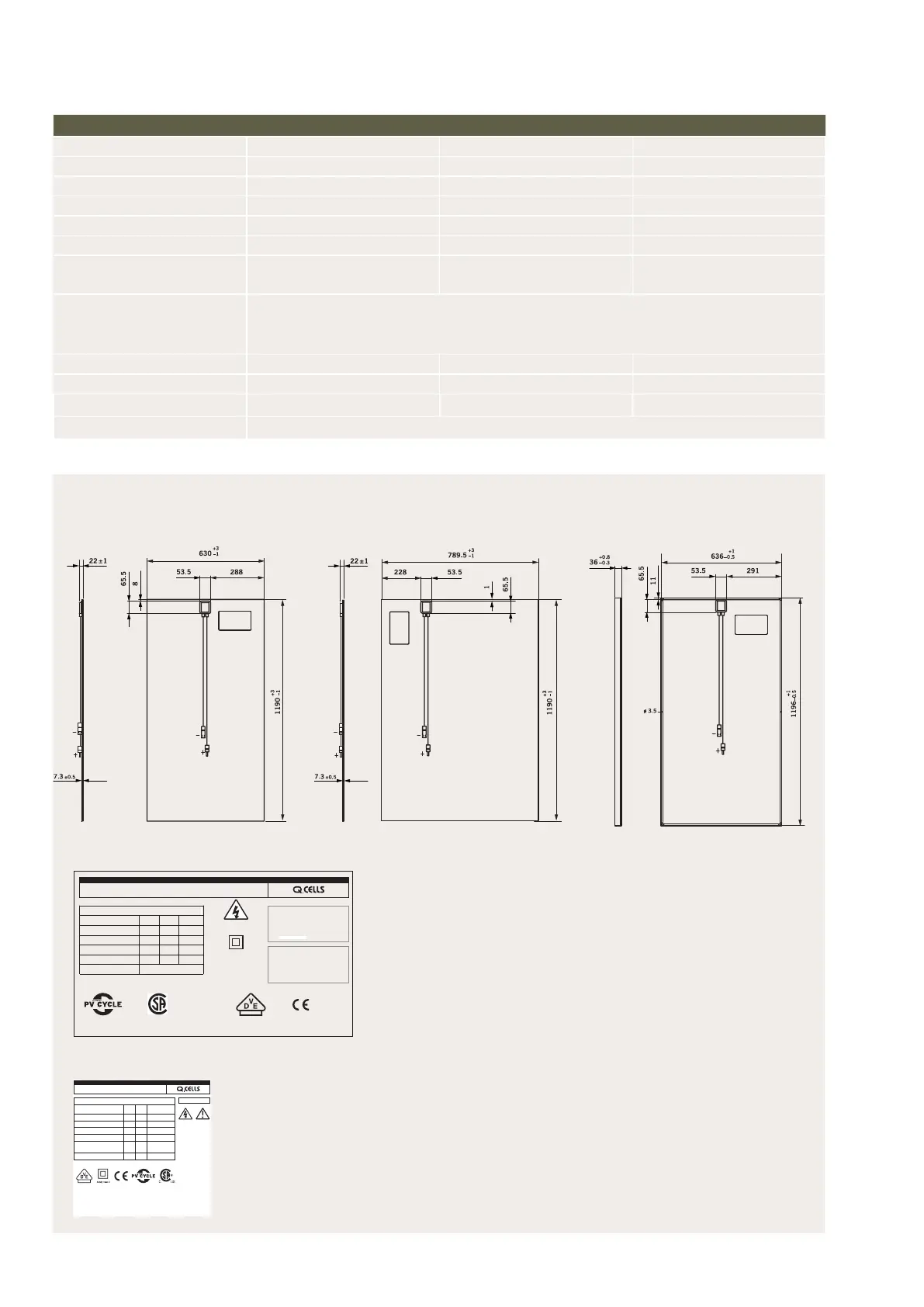
FIGURE 1: Exterior dimensions (in mm) and components for Q.SMART UF, Q.SMART UF L and Q.SMART
TECHNICAL DATA (you can nd additional data in the respectively valid data sheets at www.q-cells.com)
PRODUCT LINE Q.SMART UF (SL1) Q.SMART UF L (SL2) Q.SMART (SL1-F)
Type unframed unframed framed
Area [m²] 0.75 0.94 0.76
Weight [kg] 13.2 16.5 14.5
Max. system voltage V
sys
[V] 1,000 1,000 1,000
Max. reverse current l
R
[A] 4 4 4
Junction box Protection class IP 65 with bypass
diode
Protection class IP 65 with bypass
diode
Protection class IP 65 with bypass
diode
Connector Multicontact MC4 (safe against accidental contact, reverse-polarity protected, resistant against UV radiation
and against temperatures from -40 °C to +90°C, designed for 1000 VDC and 22 A (nominal power dependent
from surrounding temperature)
Flammability rating C C C
Snow load [Pa] 2,400 2,400 5,400
Wind load [Pa] 2,400 2,400 2,400
Certicates All modules: CE, IEC 61646 (Ed. 2), IEC 61730 (Ed. 1) application class A
Q.SMART UF Q.SMART UF L Q.SMART
Components (rear view)
1 Junction box
2 Product label
3 Connection cables (+) 855
+30 / -0
, (-) 735
+30 / -0
mm
4 Connectors (with + and - polarity)
5 Grounding points (only Q.SMART)
6 Drainage holes (only Q.SMART)
7 Frame (only Q.SMART)
7
6
6
66
5
5
4
2
1
3
4
2
1
3
4
2
1
3
FIGURE 2A: Module label of Q.SMART & Q.SMART UF
*STC: 1000 W/m², 25°C, AM 1.5 Spectrum.
Data given are rated (nominal) values.
See the
Installation and Operating Manual by Q-Cells for further information
on ap-
proved installation and use of this product.
Do not disconnect under load
Field wiring: Copper only, 14 AWG min.
Insulated for 90º C min.
Fire Rating Class C
Safety Class ll
Series Fuse: 4 A
[W]
[A]
[V]
[A]
[V]
Made in Germany
Bitterfeld-Wolfen, Germany
modules@q-cells.com
www.q-cells.com
®
USC
•
Certied UL1703
•
No 244748
•
Master Contract: 244748
FIGURE 2B: Module label of Q.SMART UF L
Q.SMART UF L 115
PERFORMANCE AT STANDARD TEST CONDITIONS*
Nominal Power
(+5 W)
Measurement accuracy Pmpp*: ± 3 %
P
mpp
[W] 115
Short circuit current I
sc
[A] 1.69
Open circuit voltage V
oc
[V] 95.1
Current at maximum power I
mpp
[A] 1.54
Voltage at maximum power V
mpp
[V] 74.7
Maximum system voltage V
sys
[V] 1000 (IEC)
600 (CSA / UL)
Weight M [kg] 16.5
*STC: 1000 W/m², 25 °C, AM 1.5 Spectrum. Data given are rated (nominal) values.
Certied
UL 1703
(No 251746)
Series Fuse: 4 A
Field Wiring:
Copper only, 14 AWG min.
Insulated for 90 º C min.
Fire Rating Class C
DANGER!
Risk of electric shock!
DO NOT connect or
disconnect plug contacts
while system is under
load current. Refer to the
Installation and Operation
Manual before installing,
operating or servicing
this unit.
49209 G1.3
EMAIL service@q-cells.com
WEB www.q-cells.com
ENGINEER ED, DESIGNED, MANUFACTURED AND QUALITY TESTED BY Q-CELLS SE.
Made in Germany
ENGINEERED, DESIGNED AND QUALITY TESTED BY Q-CELLS SE IN GERMANY
 Loading...