4. Circuit design of the QCX-mini
4.1 Block diagram and summary
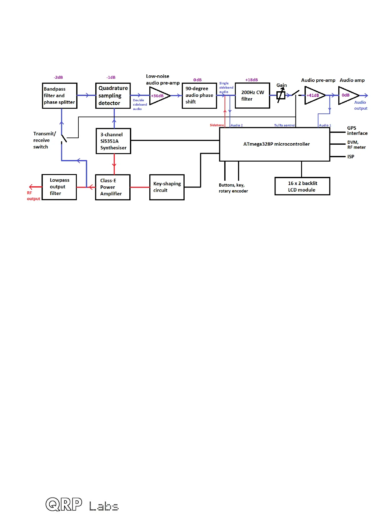
This CW transceiver is a high performance, yet simple and low cost, analogue design. The
transmitter uses a high efficiency Class-E amplifier which results in low current draw on
transmit, and inexpensive transistors with no heatsinks.
The receiver is a direct conversion type utilizing the famous high performance Quadrature
Sampling Detector, also known sometimes as the “Tayloe Detector” or even “I-Q Mixer”.
This receiver front end architecture has been used in the early Flex Software Defined
Radios, Softrock series, Norcal NC2030 and many other SDR’s and other high performance
front ends. The detector has very high third order intercept (IP3) and dynamic range, as
well as low loss.
The resulting I & Q outputs are at audio baseband and go through a 90-degree phase shift
network which cancels the unwanted sideband. A 200Hz bandwidth CW filter is followed by
more amplification and drives common earphones.
The oscillators in the transceiver are provided by the modern Si5351A digital phase locked
loop IC controlled by the microcontroller.
Permeating the entire design is microprocessor control by the ATmega328P
microcontroller. This allows implementation of a large number of functions normally only
found in radios costing 10-100x the price!
A really nice feature of the design is the built-in alignment and test equipment, which make
it possible to build, align and even debug the assembly of the radio, all with NO additional
test equipment.
4.2 Circuit diagram
79
 Loading...

