10
TD-000520-00-A
Features
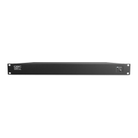
Front Panel
DEVICE:
DESIGN:
STATUS:
DESIGN STATUS
<Device Name>
<Design Name>
<Status>
1. OLED Display – Displays information about the
I/O-8 Flex's settings andstatus.
2. NEXT button – Cycles through the OLED information
pages
3. ID button – Locates the I/O-8 Flex in Q-SYS Designer
GUI and Configurator
4. POWER LED – Illuminates blue when the I/O-8 Flex is
on
5. USB Ports – USB Type A Host connectors (2)
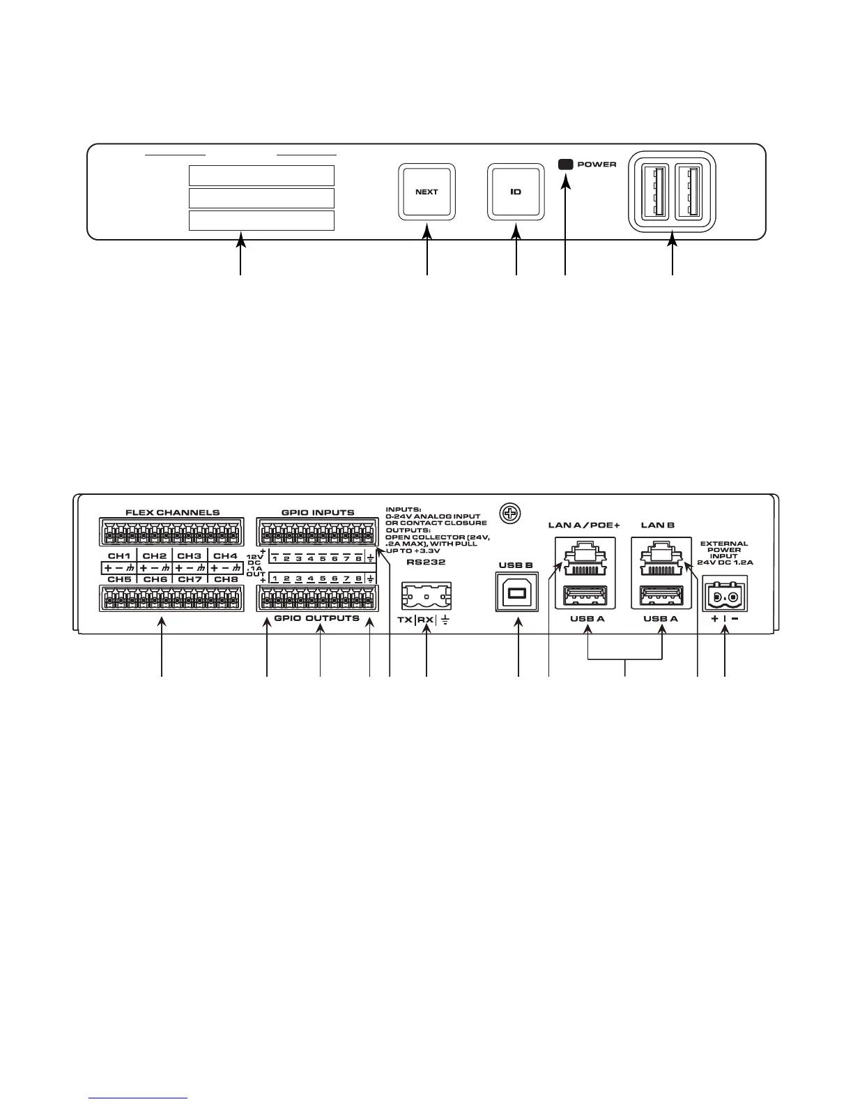
Rear Panel
1. Flex Channels – Eight user-configurable audio channels (mic/line input with optional phantom power or line output),
balanced or unbalanced - blue connectors
2. 12VDC, .1A OUT –
The + connection uses the farthest left pins (not numbered) for both GPIO INPUTS and GPIO OUTPUTS
3. GPIO OUTPUT – 8 outputs, open collector (24V, 0.2A maximum) with pull up to +3.3V (pins 1-8 equal pins 1-8 in
the Q-SYS Designer GPIO Output component)
4. Earth Ground –
The ground connection uses the farthest right pins (not numbered) for both GPIO INPUTS and GPIO OUTPUTS
5. GPIO INPUTS – 8 inputs, 0-24V analog input or contact closure (pins labeled 1-8 equal pins 1-8 in the Q-SYS
Designer GPIO Input component)
6. RS232 – Transmit and recieve, 3-pin, 5mm, Euro connector
7. USB B – USB Type B Device connector
8. LAN A/PoE+ – PoE+ power in, Q-LAN, control, VoIP, WAN streaming, AES67, etc., RJ45
9. USB A – USB Type A Host connectors
10. LAN B – Redundancy, Q-LAN, control, VoIP, WAN streaming, AES67, etc., RJ45
11. EXTERNAL POWER INPUT 24VDC 1.2A – Auxiliary power, 24VDC, 1.2A, 2-pin, 5mm, Euro connector