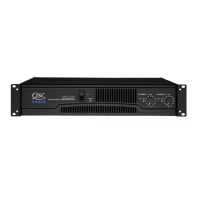
RMX Series Technical Service Manual (2RU models) 3
TD-000098-00 rev. C
Table of Contents
RMX Series Performance Specifications ...................................................................................................................................................... 2
1. Introduction ..................................................................................................................................................................................................... 5
1.1 Restriction of Hazardous Substances Directive (RoHS)................................................................................................................................ 5
1.2 QSC serial numbers ....................................................................................................................................................................................... 5
1.3 Service bulletins ............................................................................................................................................................................................. 5
1.4 The well-equipped service bench .................................................................................................................................................................. 6
1.5 Working with surface-mount components ................................................................................................................................................... 6
1.6 Series description .......................................................................................................................................................................................... 8
1.7 Technical descriptions and theory of operation ........................................................................................................................................... 8
2. Component identification and pinout ..................................................................................................................................................... 11
3. Troubleshooting: Symptoms, causes, & remedies ................................................................................................................................ 13
3.1 Excessive current draw ................................................................................................................................................................................ 13
3.2 Protection, muting, and turn-on/turn-off delay problems ......................................................................................................................... 13
3.3 Faults with signal present ........................................................................................................................................................................... 14
3.4 Instability ...................................................................................................................................................................................................... 14
3.5 Power supply and rail balancing problems ................................................................................................................................................. 15
4. RMX calibration procedures ...................................................................................................................................................................... 16
4.1 Setting bias .................................................................................................................................................................................................. 16
4.2 Setting positive and negative current limits .............................................................................................................................................. 16
5. Servicing RMX amplifiers ........................................................................................................................................................................... 18
5.1 Mechanical disassembly and re-assembly .................................................................................................................................................. 18
6. Replacement parts ....................................................................................................................................................................................... 19
6.1 RMX850 Replacement Parts ....................................................................................................................................................................... 19
6.2 RMX1450 Replacement Parts ..................................................................................................................................................................... 22
6.3 RMX1850HD Replacement Parts ................................................................................................................................................................. 25
6.4 RMX2450 Replacement Parts ..................................................................................................................................................................... 29
7. Schematics and diagrams .......................................................................................................................................................................... 33
7.1 RMX Assembly/Disassembly Diagram 1 of 2
(All models) ................................................................................................................................................................................................. 33
7.2 RMX Assembly/Disassembly Diagram 2 of 2
(All models) ................................................................................................................................................................................................. 34
7.3 RMX 850 Schematic Diagram 1 of 3
Channel 1 ................................................................................................................................................................................................... 35
7.4 RMX 850 Schematic Diagram 2 of 3
Channel 2 ................................................................................................................................................................................................... 36
7.5 RMX 850 Schematic Diagram 3 of 3
Power Supply ............................................................................................................................................................................................. 37
7.6 RMX 1450 Schematic Diagram 1 of 3
Channel 1 ................................................................................................................................................................................................... 38
7.7 RMX 1450 Schematic Diagram 2 of 3
Channel 2 ................................................................................................................................................................................................... 39
7.8 RMX 1450 Schematic Diagram 3 of 3
Power Supply ............................................................................................................................................................................................. 40
7.9 RMX 1850HD Schematic Diagram 1 of 3
Channel 1 ................................................................................................................................................................................................... 41
7.10 RMX 1850HD Schematic Diagram 2 of 3
Channel 2 ................................................................................................................................................................................................... 42
7.11 RMX 1850HD Schematic Diagram 3 of 3
Power Supply ............................................................................................................................................................................................. 43
7.12 RMX 2450 Schematic Diagram 1 of 4
Channel 1 ................................................................................................................................................................................................... 44

 Loading...