6 QSC Audio Products, LLC
Solder
1.4 The well-equipped service bench
To properly service RMX amplifiers, a technician needs the right tools. The
technician’s service bench should have the following equipment:
• Digital multimeter with RMS AC voltage and current
• Digital clamp-on ammeter
• Dual-trace oscilloscope
• Audio distortion analyzer
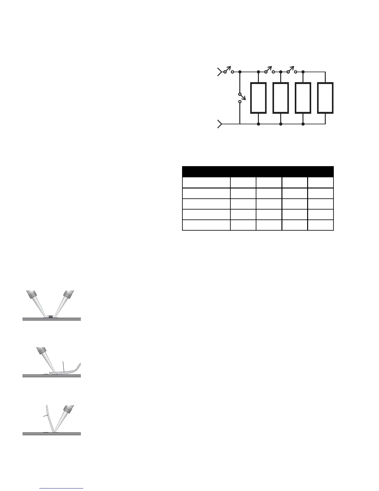
• Non-inductive load resistors, configurable as 8 ohms (min. 500 watts capacity),
as 4 ohms (min. 750 watts capacity), and 2 ohms (min. 1200 watts capacity);
see Figure 1.2 and Table 1.1.
• Variable AC voltage source, such as a Variac or Powerstat variable trans-
former, with a rated current capacity of up to 25A (for 120V models) or 12A (for
230V models)
• Low-distortion audio sine wave generator
• Philips and flat screwdrivers
• Soldering iron with a fine tip, 25–60W recommended (if you
service both RoHS-compliant and non-compliant amplifiers, you
will need separate soldering and desoldering equipment for
each)
• Appropriate rosin-core solder (use only RoHS compliant lead-
free solder for RoHS-compliant amplifers; for non-RoHS
amplifiers, use a 60/40 or 63/37 Pb/Sn alloy)
• Long-nose pliers
• Diagonal cutters
• Wire strippers
Automated test equipment, such as an Audio Precision workstation, is very useful for servicing RMX amplifiers. Contact QSC Technical
Services to obtain applicable AP test files.
Solder braid
1.5 Working with surface-mount components
RMX amplifiers, like many modern electronic products, use surface-mount technology (SMT) components
where appropriate in order to make high-density circuitry that is reliable and economical to manufacture.
SMT components in the RMX amps are used in the small-signal and control circuits, so they do not handle
significant amounts of power; therefore, they are subject to very little stress and should seldom fail.
Sometimes they do fail, or they require replacement for a performance upgrade or modification. Thus, it is
important to know how to work with SMT components.
Specialized tools and equipment exist for soldering, unsoldering, and removing SMT components quickly
and efficiently, but they are often expensive. Most SMT repairs, though, can be handled reasonably well with
common tools and equipment, such as tweezers, solder braid, and fine-tip soldering irons. The original
factory components are tacked to the board with a spot of glue, so you might have to apply some force to
break the adhesive.
Two-terminal components (resistors, capacitors, diodes, etc.)
Removal
1 Use two soldering irons, preferably about 25 to 40 watts, with fine tips.
2 With a soldering iron in each hand, hold one tip on the solder at one end of the component and the
other tip on the other end (Figure 1.3).
3 Once the solder melts on both ends, grip the component between the two tips and lift it from the
circuit board.
4 Use solder braid and a soldering iron to remove the solder from the two pads (Figure 1.4).
Figure 1.2. Load resistor bank
Table 1.1. Load resistor bank switch truth table
SW1 SW2 SW3
SW4
8Ω 8Ω 8Ω 8Ω
R1: 8 , 500W non-inductiveΩ
R2–R4: 8 , 300W min. non-inductiveΩ
R1 R2
R3 R4
SW1 SW2 SW3 SW4
∞Ω (no load)
OFF•••
8Ω
ON OFF OFF OFF
4Ω
ON ON OFF OFF
2Ω
ON ON ON OFF
0Ω (short circuit)
ON • • ON
Figure 1.5.
Figure 1.3.
Figure 1.4.

 Loading...