Electronic Temperature Monitor
ECN-27644 8 July 7, 2010
Figure 3. Wiring Diagram
RS-485 Link (optional)
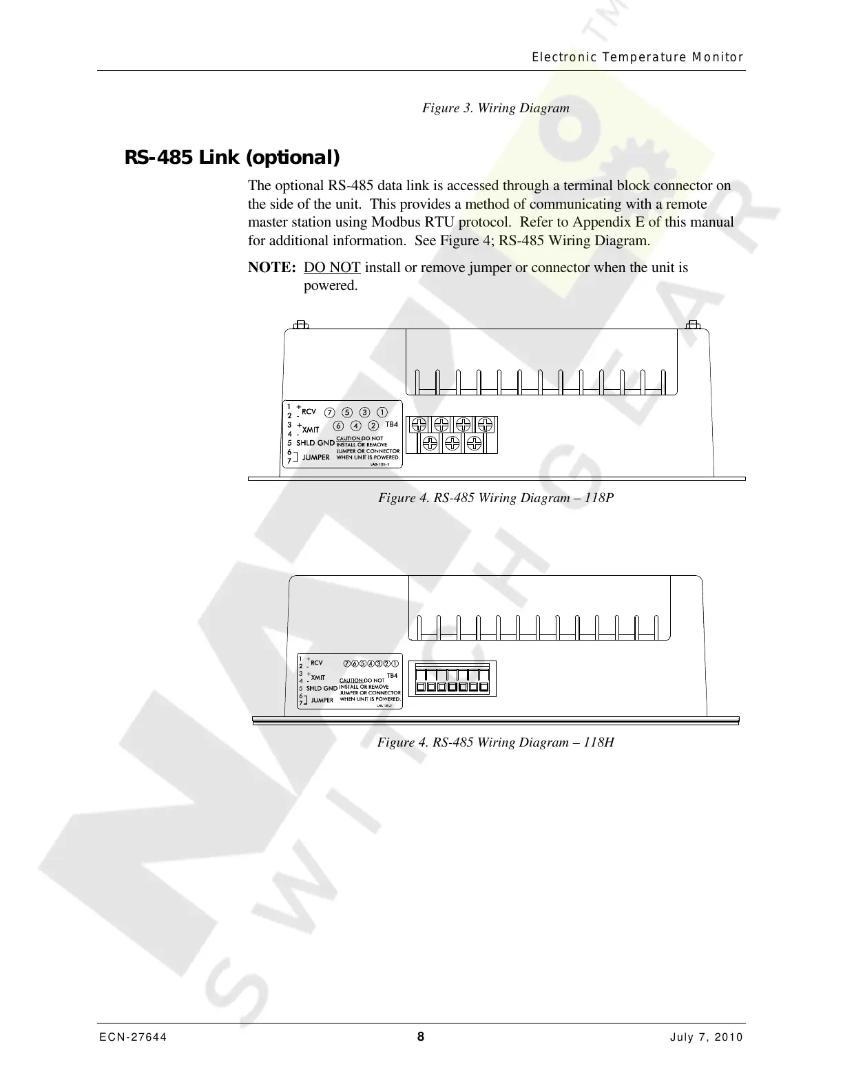
The optional RS-485 data link is accessed through a terminal block connector on
the side of the unit. This provides a method of communicating with a remote
master station using Modbus RTU protocol. Refer to Appendix E of this manual
for additional information. See Figure 4; RS-485 Wiring Diagram.
NOTE: DO NOT install or remove jumper or connector when the unit is
powered.
Figure 4. RS-485 Wiring Diagram – 118P
Figure 4. RS-485 Wiring Diagram – 118H
Courtesy of NationalSwitchgear.com
 Loading...