Electronic Temperature Monitor
ECN-27644 7 July 7, 2010
close. The operation of this relay can be changed to be opposite of
that described above (failsafe) through the software configuration.
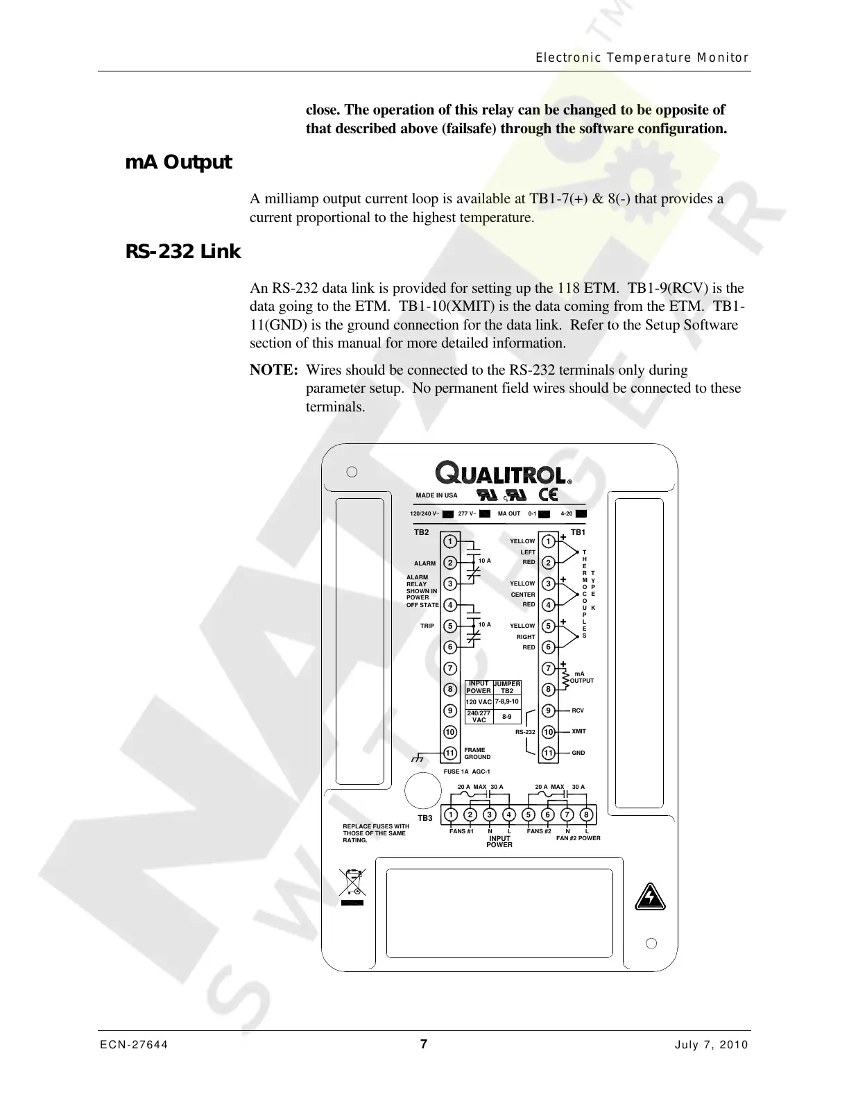
mA Output
A milliamp output current loop is available at TB1-7(+) & 8(-) that provides a
current proportional to the highest temperature.
RS-232 Link
An RS-232 data link is provided for setting up the 118 ETM. TB1-9(RCV) is the
data going to the ETM. TB1-10(XMIT) is the data coming from the ETM. TB1-
11(GND) is the ground connection for the data link. Refer to the Setup Software
section of this manual for more detailed information.
NOTE: Wires should be connected to the RS-232 terminals only during
parameter setup. No permanent field wires should be connected to these
terminals.
RS-232
XMIT
10 10
FANS #1
20 A MAX
FUSE 1A AGC-1
11
TB3
1
FAN #2 POWER
30 A
GND
N L
FANS #2
N
30 A
32 4
GROUND
FRAME
20 A MAX
5 6 7
11
L
8
MADE IN USA
ALARM 2
6
8
9
7
4
TRIP
5
3
TB2
1
RED
H
10 A
2
RCV
OUTPUT
mA
RED
6
8
9
7
+
YELLOW
YELLOW
CENTER
10 A
RED
4
5
RIGHT
+
3
+
O
S
E
L
P
U K
M
Y
C
O
E
P
R
E
T
TB1
YELLOW
1
LEFT
+
MA OUT 0-1
4-20
T
REPLACE FUSES WITH
THOSE OF THE SAME
RATING.
120/240 V~
277 V~
ALARM
SHOWN IN
POWER
OFF STATE
RELAY
120 VAC
240/277
VAC
INPUT
POWER
7-8,9-10
8-9
JUMPER
TB2
INPUT
POWER
Courtesy of NationalSwitchgear.com

 Loading...