Do you have a question about the Qualitrol 118 Series and is the answer not in the manual?
Monitors up to 3 thermocouples, displays temps, and operates relays for dry type transformers.
Step-by-step instructions for mounting, power connection, and wiring the temperature monitor.
Describes unit use during transformer operation and system testing procedures.
Detailed technical specifications of the unit's capabilities and performance characteristics.
Instructions for configuring the monitor using dedicated software and parameters.
Procedure for field adjustment of monitor setpoints without computer access.
Installation and testing procedures to ensure accurate thermocouple readings.
Explanation of error codes, their causes, and the corresponding system responses.
Specific requirements and considerations for using the monitor in the European community.
Setup and usage instructions for the Modbus communication protocol.
Details on how the 118 and 118H models mount in a panel cutout with dimensions.
Connection details for primary power supply and voltage jumper settings.
Instructions for connecting Type K thermocouples to the unit's input terminals.
Explanation of Alarm and Trip relay contact states and fail-safe settings.
Description of the proportional milliamp output signal for temperature monitoring.
Information on the RS-232 data link for unit setup and configuration parameters.
Details on the optional RS-485 port for Modbus RTU communication.
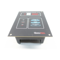
Describes the 3-digit LED display and individual status LEDs for temperature and status.
Explains status LEDs (FAN, ALARM, TRIP) and the internal buzzer function.
Explains the functions of the MANUAL FAN and SILENCE/TEST buttons.
Details the built-in function to periodically activate fans for a set duration and interval.
Steps to install the ETM Configuration software from the provided CD.
Options for managing configuration files (new, open) and selecting the communication port.
Setting parameters like active channels, setpoints, relay modes, and fan exerciser.
Protecting TC connection terminals from air currents for accurate readings.
Procedures for testing ETM accuracy using a millivolt signal and reference.
Details on failed sensors, converters, EEPROM, display, microprocessor, and connections.
Mounting requirements, mains supply, grounding, and circuit breaker provisions.
Types and locations of the 20A fan fuse and 1A electronic section fuse.
Wiring diagram and function of the RS-485 terminal block connector.
Procedure for setting baud rate, parity, stop bits, and protocol via front panel.
Table detailing Modbus registers for temperature, status, and stored values.
Table listing diagnostic status, phase status, setpoints, and data sent to registers.
The QualiTROL 118 Series Electronic Temperature Monitor (ETM) is a sophisticated device designed to monitor and manage the temperature of ventilated dry-type transformer windings. It can track up to three Type K thermocouples simultaneously, providing real-time temperature readings and activating relays based on predefined setpoints. This ensures the safe and efficient operation of transformers by preventing overheating.
The primary function of the 118 ETM is to continuously monitor the temperature of up to three transformer windings. It displays the current temperature for each winding, as well as the highest temperature recorded among them. When the maximum stored temperature is displayed, the unit indicates which winding caused that maximum reading.
The ETM incorporates several output relays to control cooling fans and signal alarm or trip conditions. A high-contact rating SPST relay, protected by an internal fuse, is dedicated to controlling cooling fans. An optional second fan control relay with its own power feed and fuse can also be integrated. The unit operates a SPDT (form C) relay for alarm conditions, which is typically energized in its normal state to ensure a fail-safe mechanism, meaning a power failure will trigger an alarm. Another SPDT (form C) relay is used for trip conditions, activating when temperatures exceed a critical threshold. This trip relay is usually de-energized in its normal state.
An audible buzzer provides immediate notification when an alarm condition is met. This buzzer can be silenced manually without affecting the alarm relay's state. In the event of a thermocouple open circuit, the ETM detects the fault, activates the alarm, and displays "---" for the faulty channel. This ensures that a single sensor failure does not prevent the unit from monitoring the remaining healthy channels.
For remote monitoring and control, the ETM offers a 0 to 1 mA output (or an optional 4 to 20 mA output) proportional to the highest input temperature. An RS-232 data link is provided for configuring programmable parameters, and an optional RS-485 communications port with Modbus protocol allows for integration into larger control systems.
The 118 ETM features a user-friendly interface with a 3-digit, seven-segment LED display that shows temperatures from 0°C to 250°C. The display cycles through each winding temperature and the maximum stored temperature, with individual LEDs indicating the source of the displayed temperature.
Three status LEDs provide a quick visual indication of the output relays' status: a yellow FAN LED for fan activation, a red ALARM LED for alarm conditions, and a red TRIP LED for trip conditions.
Push-buttons on the front panel allow for manual control and testing. The "MANUAL FAN" button can force the cooling fans ON, with a red LED indicating manual fan activation. Pressing it again releases the manual control, though fans will remain ON if the temperature is above the fan ON setpoint. The "SILENCE/TEST" button serves a dual purpose: it silences the audible alarm when active and initiates a test sequence when not sounding. The test sequence cycles through the fan ON, alarm, and trip setpoints, lights all LEDs, sounds the buzzer, and displays the internal ambient temperature and "888" on the display. The "MAX RESET" button clears the memory of the maximum stored temperature, allowing the current highest winding temperature to become the new maximum.
A built-in "Fan Exerciser" function can be configured to periodically turn the fans ON for a short duration, ensuring their operational readiness. The run time and interval for this function are programmable.
The ETM's configuration can be managed through a Windows-based software program via the RS-232 port. This software allows users to set parameters such as active channels, fan/alarm/trip setpoints and switching differentials, trip relay fail-safe status, fan exerciser settings, SCADA remote output source (hottest or center phase), and reverse thermocouple sense feature. The reverse thermocouple sense feature helps detect incorrect wiring by triggering a fault mode if the thermocouple temperature is significantly colder than the internal ambient temperature.
The ETM is designed for ease of maintenance and fault detection. If a thermocouple is not connected to an input, the terminals must be shorted to prevent alarm conditions, and the channel can be turned OFF using the setup software. This will cause the channel to display the internal temperature of the ETM.
The system continuously self-checks for proper operation. In case of a detected failure, the fans are turned ON, and the unit enters an alarm state. Error codes are displayed to help diagnose issues:
The unit uses two types of fuses: 20A fuses for fan current monitoring and 1A fuses for the electronic section. These are accessible for replacement by trained personnel after power is turned off. The 20A fuse is on the rear, requiring a tool for access, while the 1A fuse is located above the FAN#1 terminal block.
| Display | 2 line alphanumeric LCD |
|---|---|
| Power Supply | 24 VDC or 100-240 VAC |
| Communication | RS-485 |
| Output Options | 4-20mA |
| Communication Protocol | Modbus RTU |