810-1902-03 Rev D TM1 Installation Guide
12
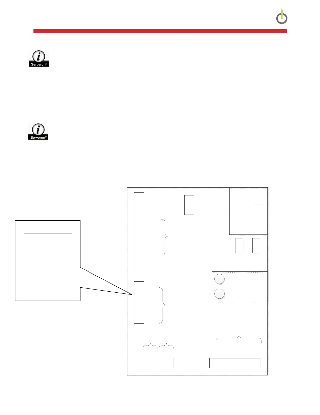
NOTE: Gland Fitting Information –
Large Gland (AUX1 and AUX2) – Accepts a multi-conductor cable with 0.31” to 0.63” OD
Hole size is 0.850”
Small Gland (Power) – Accepts a multi-conductor cable with 0.2” to 0.47” OD
Hole size is 0.690”
I/O Connections
1) Refer to the figure below to identify the various wiring connectors.
NOTE: IO cable must be shielded and grounded
2) The wiring connections specific to the cable coming from the optional Oil
Moisture/Temperature probe are shown below.
3) Terminate any additional wiring (alarm/service relays, 4-20mA inputs/outputs) per the
diagram below, which is also located on the inside of the TM1 cover.
Figure 12: Connection Details
CommGND
CTS/RXB
RX/RXA
RTS/TXB
TX/TXA
OutGND
(2) -
(2) +
(1) -
(1) +
(0) -
(0) +
DCD
DTR
FrameGND
J21
1
15
4-20
Outputs
FrameGND
IN GND
(1) RTN
(1) IN
(1) PWR
(0) RTN
(0) IN
(0) PWR
J22
1
8
4-20
Inputs
J4
17
COM
NC
NO
COM
NC
NO
FrameGND
SRVPWR
J3
110
COM (0)
NC (0)
NO (0)
COM (1)
NC (1)
NO (1)
COM (2)
NC (2)
NO (2)
FrameGND
PRGM
F1
F2
1A, 250VAC, 3AG(T)
Earth GND
L2
L1 1
3
Input Voltage
100-240 VAC 50/60Hz
Jumper Settings
3-4 232
2-3 485-Full
1-2 485-Half
J6
1
4
PRGM
Interface
USB A
Mini B
Comms
Interface
Serial Configuration
Input Voltage
Terminal Connection not
located on this board
E+E 364 MIO Probe
GND (PINK) Pin 7
CH2 (GRY) Pin 5
CH1 (YEL) Pin 2
+24V (RED) Pin 1