QUANTECH
FORM QTC2-eg1 (515)
26
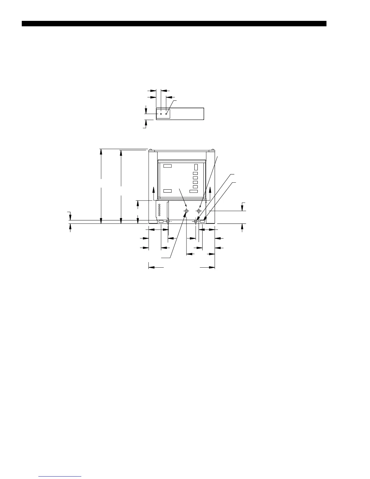
Unit Dimensions - English (Cont'd)
QTC2030T
44 5/16"
BASE WIDTH
50 1/16"
49 1/4"
6 3/4"
3 15/16"
LEFT END
BOTTOM OF PANEL
7/8" TYP.
VIEW B-B
POWER: SINGLE POINT SUPPLY WITH TERMINAL BLOCK
19"
10 3/4"
8 1/2"
2" ANSI/AWWA C-606
CONN (typ)
B
B
15 1/2"
TO ACCESS PANEL 13 3/8"
8 5/16"
12 13/16"
8 5/16"
12 13/16"
2" DIA
(2) 3.0 X 1.50
RIGGING HOLES
BOTH ENDS
IN
OUT
LD18675
NOTE:
Placement on a level surface of free of obstructions (including snow, for winter operation) or air circulation ensures rated performance, reli-
able operation, and ease of maintenance. Site restrictions may compromise minimum clearances indicated below, resulting in unpredictable
airowpatternsandpossiblediminishedperformance.Theunitcontrolswilloptimizeoperationwithoutnuisancehigh-pressuresafetycut-outs;
however, the system designer must consider potential performance degradation. Access to the unit control center assumes the unit is no
higherthanonspringisolators.Recommendedminimumclearances:Sidetowall–6';reartowall–6';controlpaneltoendwall–4'0'';
top–noobstructionsallowed;distancebetweenadjacentunits–10'.Nomorethanoneadjacentwallmaybehigherthantheunit.