Chapter 5 Service Instructions
HF Series X-ray Generators - Service Manual Revision W
Quantum Medical Imaging, LLC
5-81
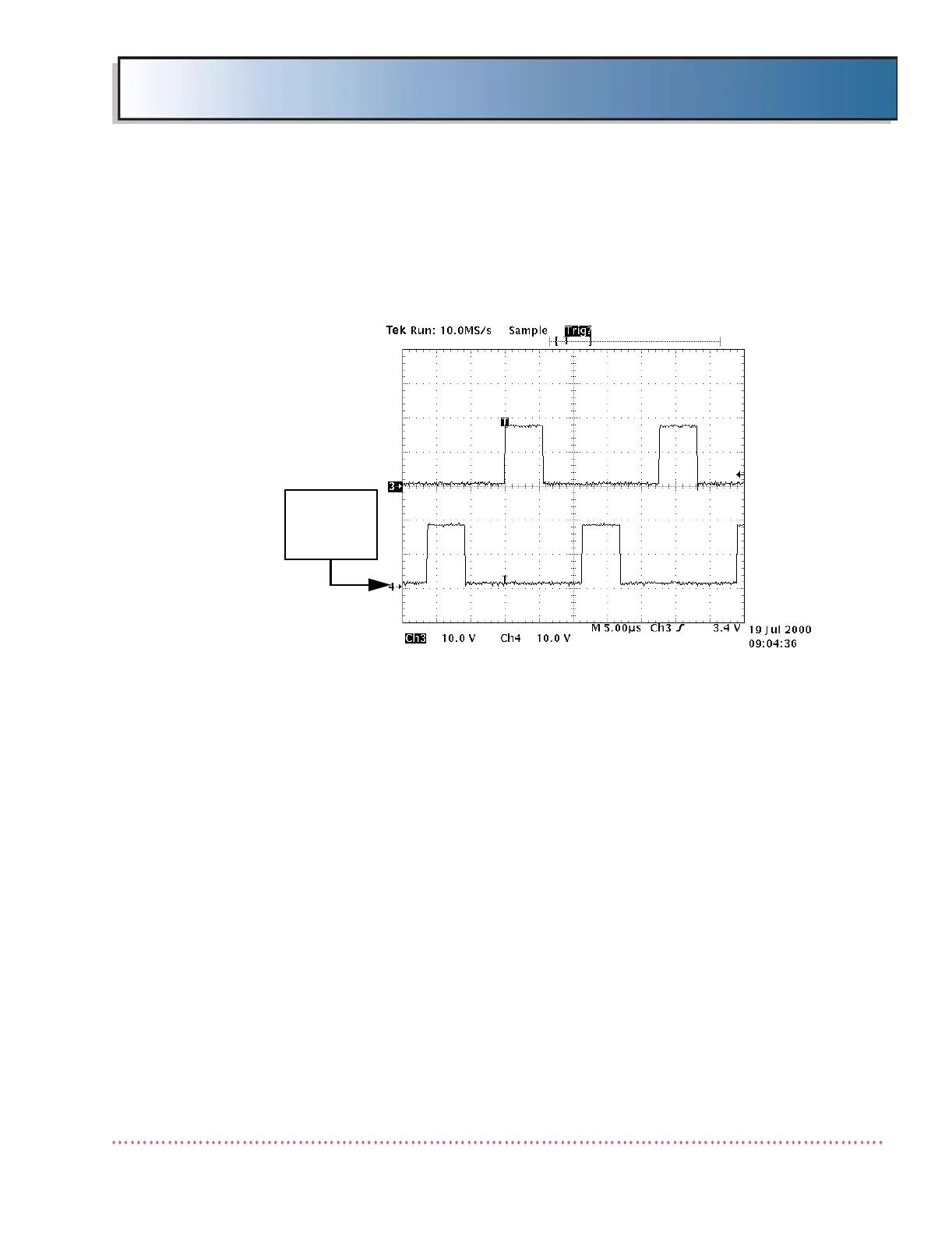
9. Press the EXPOSE key. Verify the pulses at each test point are
5.5 µsec. wide and the rising edges of the pulses at A2TP21 are
12 µsec. from the rising edges of the pulses at A2TP22 (see Fig-
ure 5-10 for correct waveforms).
Figure 5-7. KVP Control Board A2TP21 and A2TP22/A2TP23
and A2TP24 Waveforms
10. If the time between the pulses is not 12 µsec., adjust the oscillo-
scope time base to 0.5 µsec./div. and adjust Anode Output Poten-
tiometer A2R3 to obtain 12.0 ±0.1 µsec.
11. Move oscilloscope probes to A2TP23 and A2TP24.
12. Press the EXPOSE key. Verify the pulses at each test point are
5.5 µsec. wide and the rising edge of the pulses at A2TP23 are 12
µsec. from the rising edges of the pulses at A2TP24.
13. If the time between the pulses is not 12 µsec., adjust the oscillo-
scope time base to 0.5 µsec./div. and adjust Cathode Output
Potentiometer A2R34 to obtain 12 µsec. ±0.1 µsec.
14. Re-insert plugs in connectors A2J7 (anode) and A2J8 (cathode)
on KVP Control Board A2.
15. Perform KV, Filament and MA calibration procedures (refer to
Chapter 3, Calibration (ODYSSEY) or Appendix B (DiRex Integra-
tion generators), or Appendix D (all other integrated generators).