Chapter 5 Installation of 5U enclosures 39
12Gb/s
12Gb/s
0A
0B
1
2
7
8
4
3
6
5
9
10
1
2
4
3
6
5
7
8
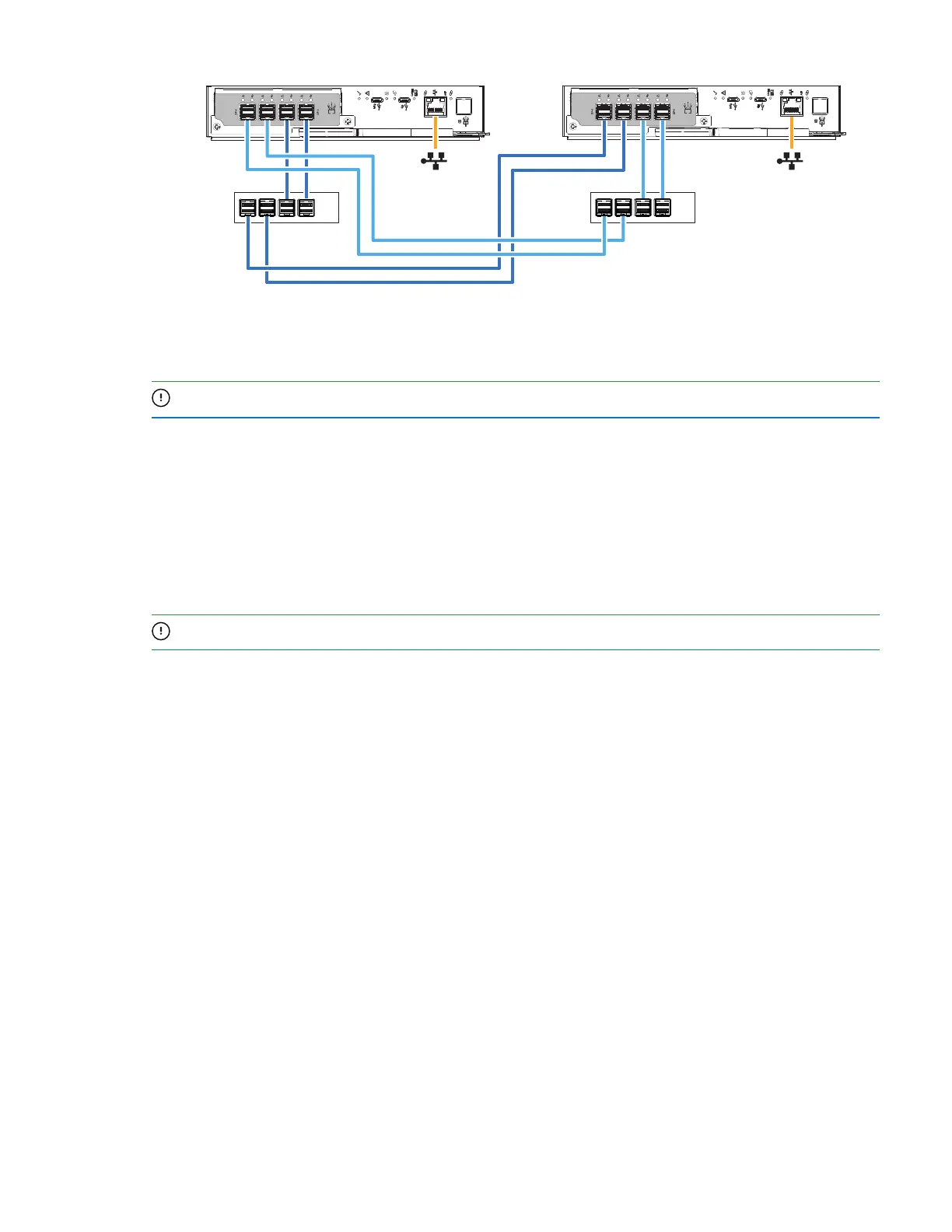
Figure 31 Sample data and management cabling among 5U controllers and host system switches
2. Take the following actions to connect Controller 0A to its related expansion modules. The example below
has 3 expansion enclosures directly below the storage enclosure.
IMPORTANT Best practice is to use the expansion Port A for input and Port C for output.
a. Insert a mini-SAS data cable into the left controller, Controller 0A, then connect the other end to SAS
port A in the first expansion enclosure, 1A.
b. Insert a mini-SAS data cable from SAS port C in the first expansion enclosure, 1A, and connect the other
end to SAS port A in the second expansion enclosure, 2A.
c. Insert a mini-SAS data cable from SAS port C in the second expansion enclosure, 2A, and connect the
other end to SAS port A in the third expansion enclosure, 3A.
3. Take the following actions to connect Controller 0B to its related expansion modules.
IMPORTANT Best practice is to use the expansion Port A for input and Port C for output.
a. Insert a mini-SAS data cable into the right controller, Controller 0B, and connect the other end to SAS
port A in the third expansion enclosure, 3B.
b. Insert a mini-SAS data cable from SAS port C in the third expansion enclosure, 3B, and connect the
other end to SAS port A in the second expansion enclosure, 2B.
c. Insert a mini-SAS data cable from SAS port C in the second expansion enclosure, 2B, and connect the
other end to SAS port A in the first expansion enclosure, 1B.
 Loading...


