Chapter 8 Storage enclosure management 65
To make this as clear as possible, depictions are of a simplified version of four-port controller, where green
cables show replication traffic and blue cables show I/O traffic.
Figure 48 Sample of three switches for co-located controller enclosures, multiple host servers
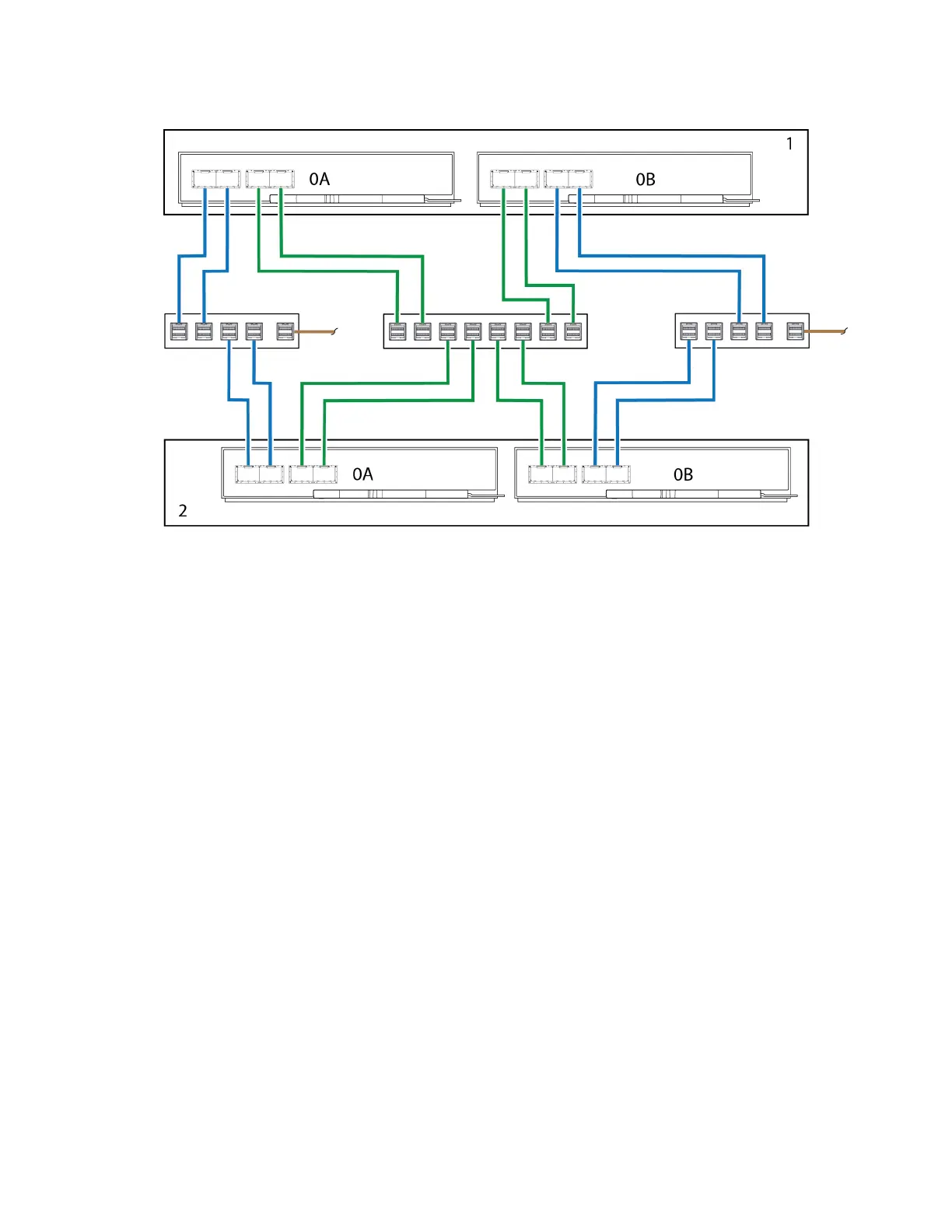
Co-located replication with single switch and server
In cases where you use a single switch connected to a single host server that is logically functioning as
multiple servers, an example of optimal cabling dedicates a pair of cables connected to each controller for I/O
traffic and the other pair connected to each controller for replication traffic.
Sample cabling for the first controller enclosure:
l
Two SFP I/O cables connect Controller 0A and two more connect Controller 0B to the switch.
l
Two SFPreplication cables connect Controller 0A and two more connect Controller 0B to the switch.
Sample cabling for the second controller enclosure:
l
Two SFP I/O cables connect Controller 0A and two more connect Controller 0B to the switch.
l
Two SFP replication cables connect Controller 0A and two more connect Controller 0B to the switch.
To make this as clear as possible, depictions are of a simplified version of four-port controller, where green
cables show replication traffic and blue cables show I/O traffic.
 Loading...


