70Chapter 9 Hardware installation and configuration issues
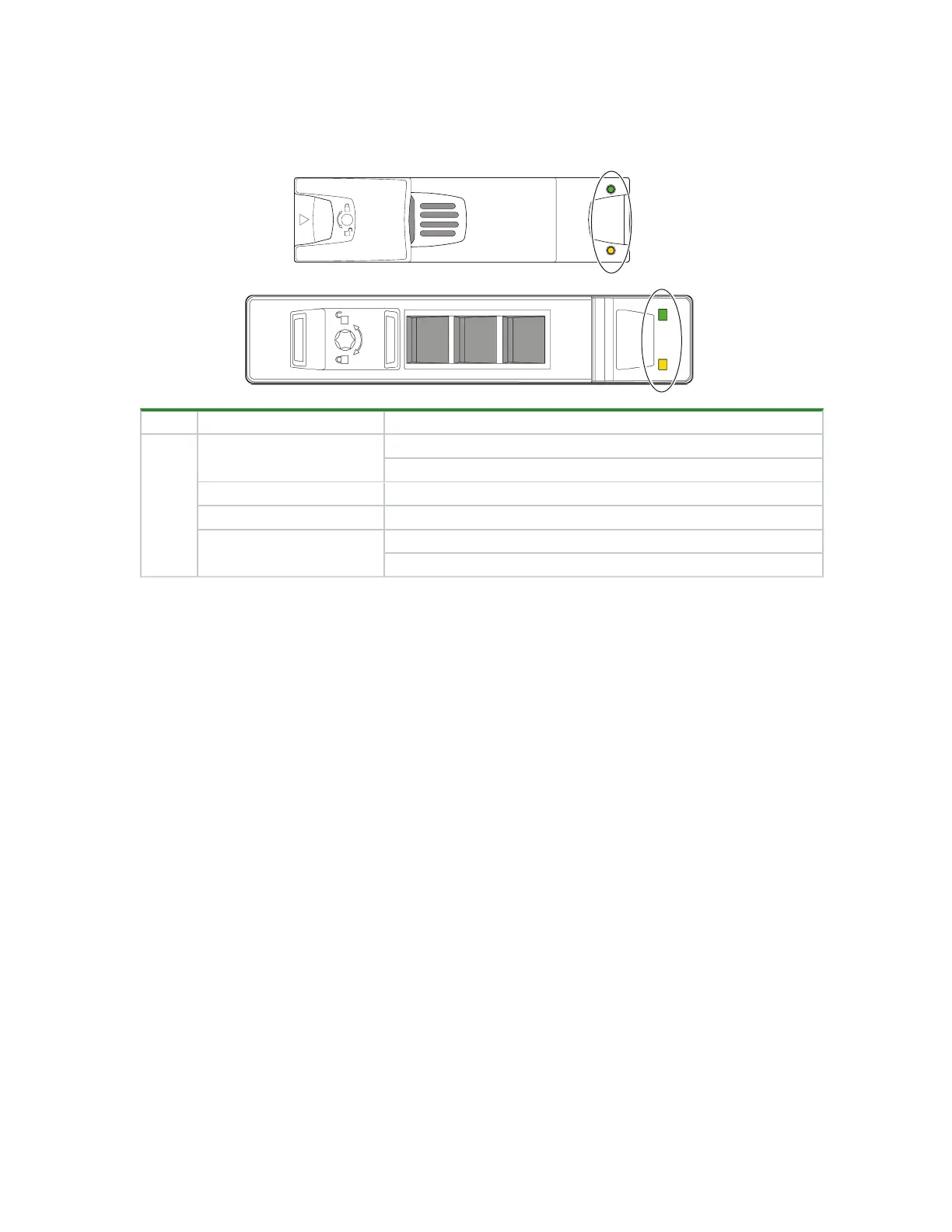
Drive carrier fault LED
The drive module in its carrier (DDIC) uses an amber LED to identify various states and fault conditions. The
asterisk (*) indicates a fault condition.
Color State Status
Amber
On*
The drive module has a hardware fault, so replace as soon as possible
The power control circuit has a hardware fault
Fast flash (1s on, 1s off) Unit identification (UID) bit is set
Slow flash*(3s on, 1s off) Failed array
Off
Drive is functioning normally
No AC power is present
Figure 52 2U12 and 2U24 fault LEDs on carrier bezel
Controller module fault LEDs
The controller module (CM) has several ports, some with independent status LEDs. The illustration below is of
the SAS four-port version of the CM. The amber LEDs listed below are the only ones that provide fault
condition status. The asterisk (*) indicates a fault condition.
 Loading...


