Chapter 1: Components
4U56 Drive System
QX and QXS Setup Guide 28
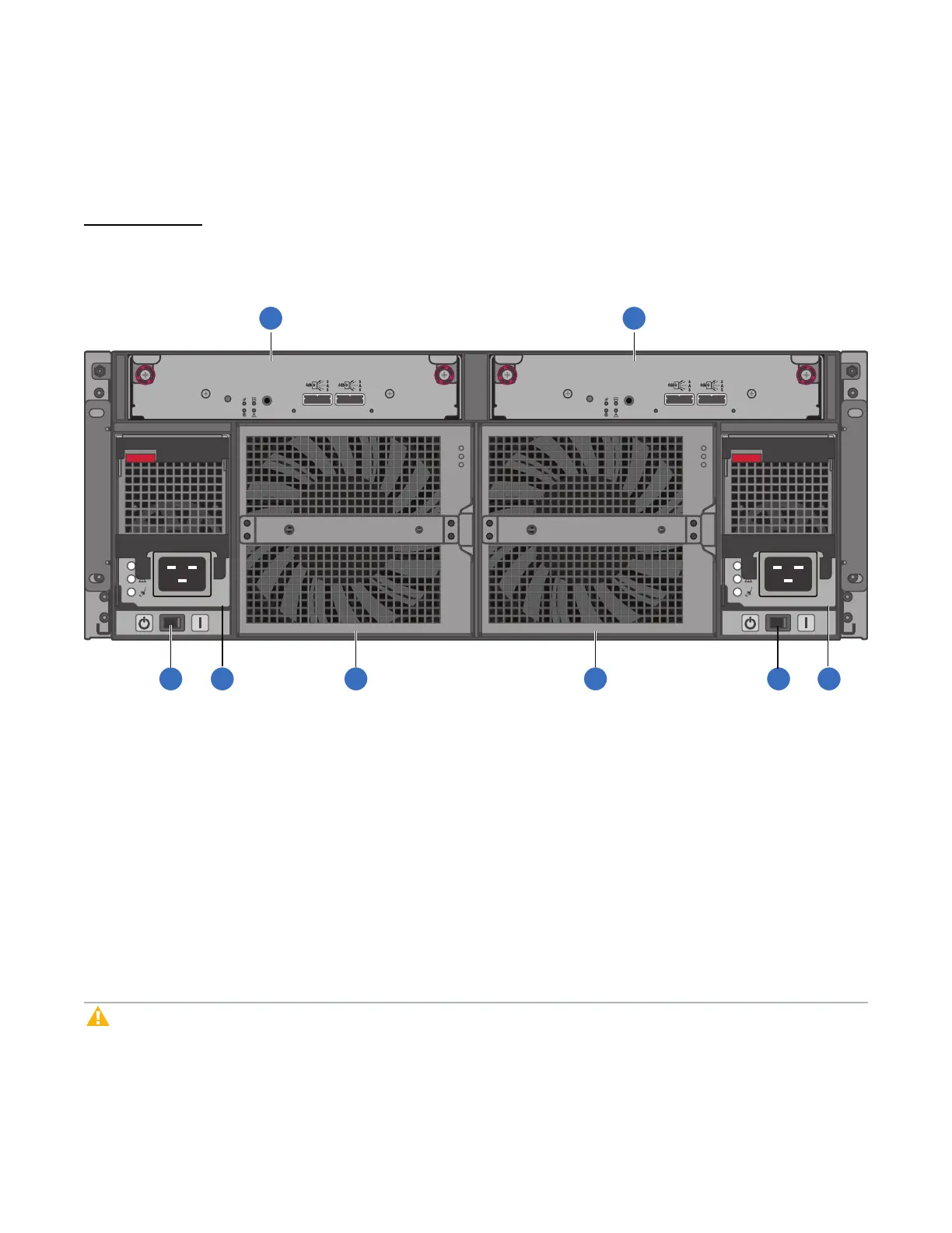
56 Drive Expansion chassis: Rear Panel Components
Figure 35 below and table display and identify important components that comprise the rear panel layout of
a 56-Drive Expansion chassis.
Figure35:56 Drive Expansion Chassis: Rear Panel Layout
LINKLINK
SERVICE
IN OUT
LINKLINK
SERVICE
IN OUT
1. ExpansionI/OModuleA
2. ExpansionI/OModuleB
3. ACPowerSupplySwitch
4. PowerSupplyModule
5. FanModule
An expansion chassis accommodates the following:
l Two expansion I/O modules of the same type within the Expansion I/O Module slots (see callouts 1 and
2 above)
l Two power supplies (CRU) of the same type either both AC or both DC— within the two power supply
slots (see two instances of callout 4)
l Separate power supply switches (see two instances of callout 3)
l Two fan control modules (see two instances of callout 5)
Caution:An expansion I/O module must be installed in each Expansion I/O Module slot to ensure
sufficient airflow through the chassis during operation.
 Loading...


