GV58LAU User Manual
TRACGV58LAUUM001 – 9 –
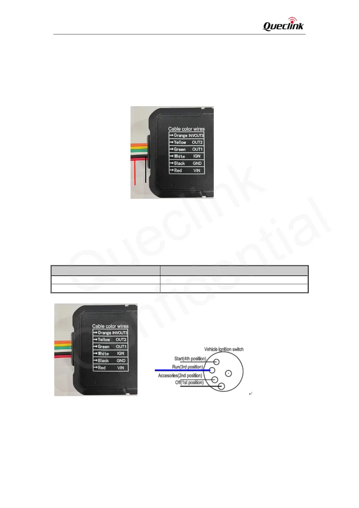
2.4. Power Connection
VIN(Red) and GND(Black) are the power input pins. The input voltage range for this device is
from 8V to 32V. The device is designed to be installed in vehicles that operate on 12V or 24V
vehicle without the need for external transformers.
Figure 3: Typical Power Connection
2.5. Ignition Detection
Table 6: Electrical Characteristics of Ignition Detection
Figure 4: Typical Ignition Detection
IGN(White) is used for ignition detection. It is strongly recommended to connect this pin to the
ignition key “RUN” position as shown above.
An alternative to connecting to the ignition switch is to find a non-permanent power source that
GND
IGN (White)

 Loading...