NB-IoT Module Series
BC660K-GL Hardware Design
BC660K-GL_Hardware_Design 26 / 57
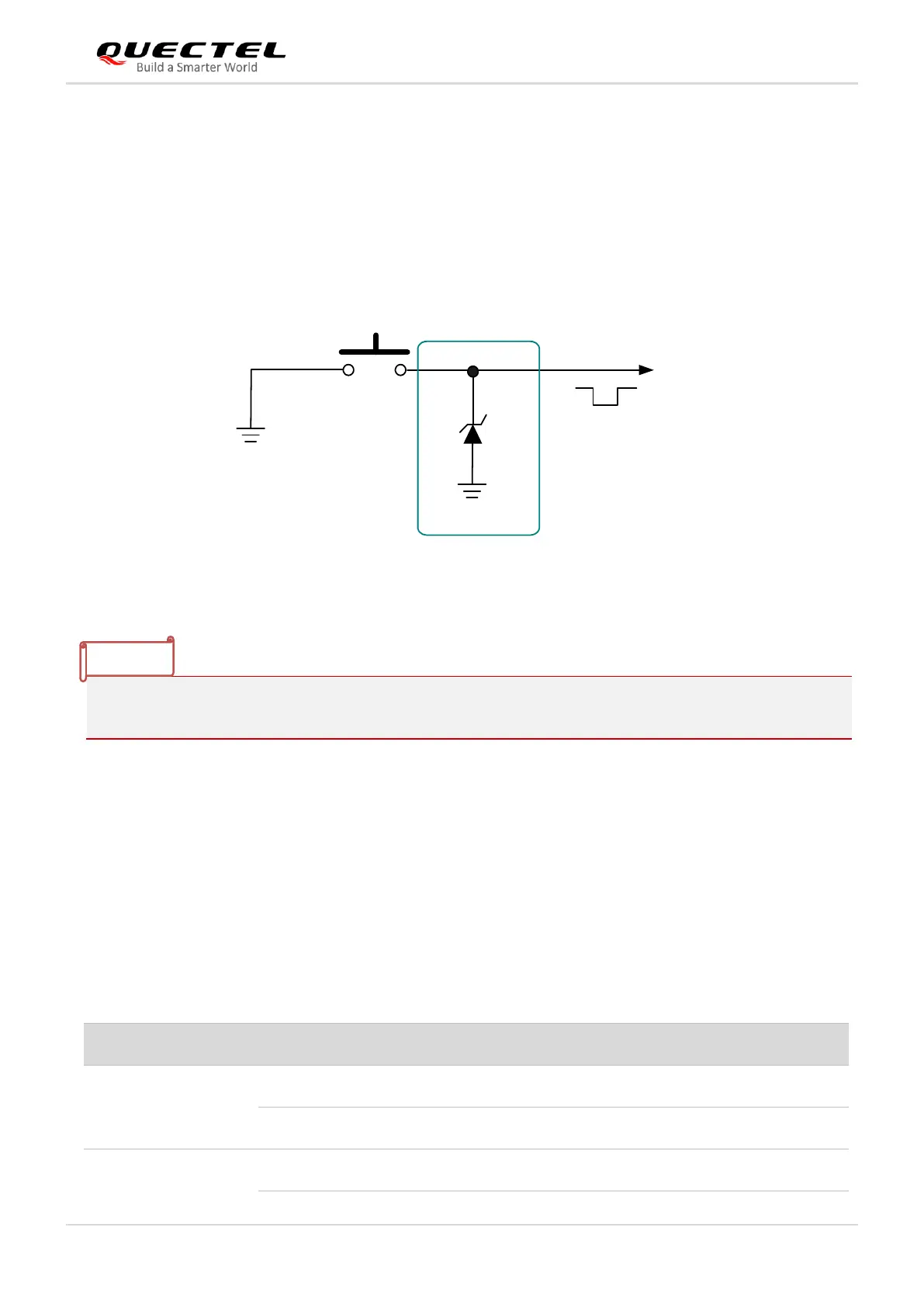
In the process of module reset or powering on, drive and keep the BOOT pin low and the module will
enter the download mode.
In the download mode, the firmware can be downloaded through the main serial port. After the download
is completed, the module needs to be reset to exit from the download mode.
A reference design is shown below
3.7. UART Interfaces
The module provides two UART ports: the main UART port and the debug UART port. The module is
designed as DCE (Data Communication Equipment), following the traditional DCE-DTE (Data Terminal
Equipment) connection.
Table 11: Pin Definition of UART Interfaces