NB-IoT Module Series
BC950K-GL_TE-B_User_Guide 22 / 28
4.2.2. Operation Procedures of Using Multi Boards
1. Install a driver for STM32 Nucleo-64 board, which can be downloaded from the following link:
http://www.st.com/content/st_com/en/products/evaluation-tools/product-evaluation-tools/mcu-eval-
tools/stm32-mcu-eval-tools/stm32-mcu-nucleo/nucleo-l476rg.html;
2. Install a USB-to-UART driver which can be downloaded from the following link:
https://www.wch.cn/downloads/USBMSER_exe.html ;
3. Remove two 0 Ω resistors (SB13 and SB14) by soldering iron, and then solder them onto SB62 and
SB63 respectively;
4. Short-circuit pin 1 & 2 of CN2, pin 3 & 4 of CN2, pin 1 & 2 of JP5 and pin 1 & 2 of JP6;
5. Insert a Micro-SIM card into J0401, and please note that an NB-IoT USIM card should be selected;
6. Connect the rod antenna with SMA connector on J0306 (RF antenna connector);
7. Switch S0301 (UART switch) to “UART-TO-MCU” state;
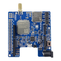
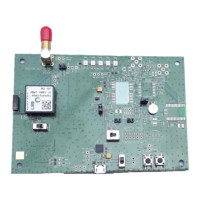
8. Connect TE-B with STM32 Nucleo-64 board via Arduino interface, and connect J0301, J0303, J0304
and J0308 of TE-B to CN5, CN6, CN8 and CN9 respectively.
9. Connect CN1 of STM32 Nucleo-64 board with PC via a Mini USB cable. After powering on
BC950K-GL, device information will be shown on the “Device Manager” of PC.
Figure 13: STLink Interface Displayed on PC
4.2.3. Description of Pin Connection
The table below shows the pin connection between TE-B and STM32-L476RG MCU, one kind of STM32
Nucleo-64 board.