LPWA Module Series
BG77 Hardware Design
BG77_Hardware_Design 42 / 76
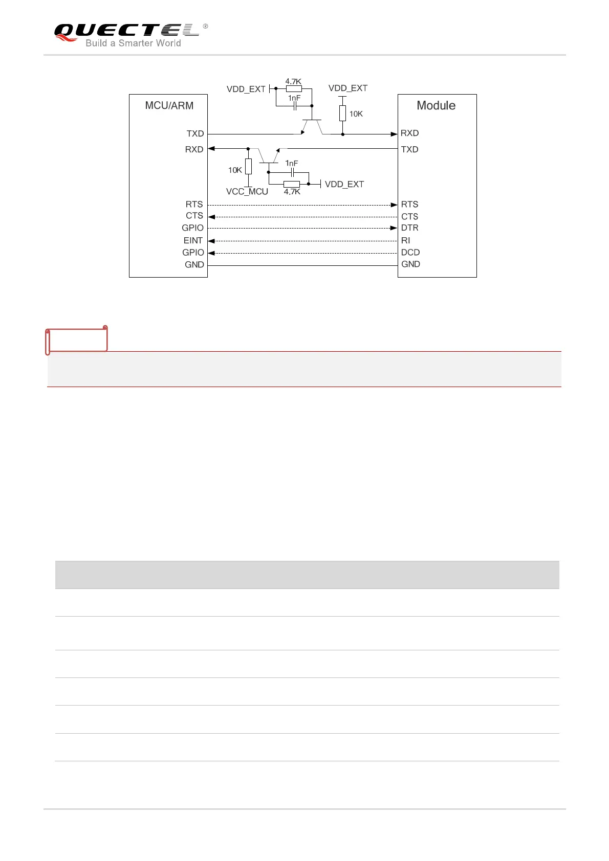
Figure 18: Reference Circuit with Transistor Circuit
Transistor circuit solution is not suitable for applications with high baud rates exceeding 460Kbps.
3.12. PCM and I2C Interfaces*
BG77 provides one Pulse Code Modulation (PCM) digital interface and one I2C interface. The following
table shows the pin definition of the two interfaces which can be applied on audio codec design.
Table 16: Pin Definition of PCM and I2C Interfaces
Pin Name Pin No. I/O Description Comment
PCM_CLK 3 DO PCM clock output 1.8V power domain
PCM_SYNC 35 DO
PCM frame synchronization
output
1.8V power domain
PCM_DIN 2 DI PCM data input 1.8V power domain
PCM_DOUT 34 DO PCM data output 1.8V power domain
I2C_SCL 37 OD I2C serial clock Require external pull-up to 1.8V
I2C_SDA 5 OD I2C serial data Require external pull-up to 1.8V
NOTE