EasyManuals Logo

Quectel EG915U Series User Manual

Quectel EG915U Series
92 pages
To Next Page IconTo Next Page
To Previous Page IconTo Previous Page
Page #48 background imageLoading...
Page #48 background image
LTE Standard Module Series
EG915U_Series_Hardware_Design 47 / 81
Table 15: Pin Definition of Debug UART Interface
Table 16: Auxiliary UART
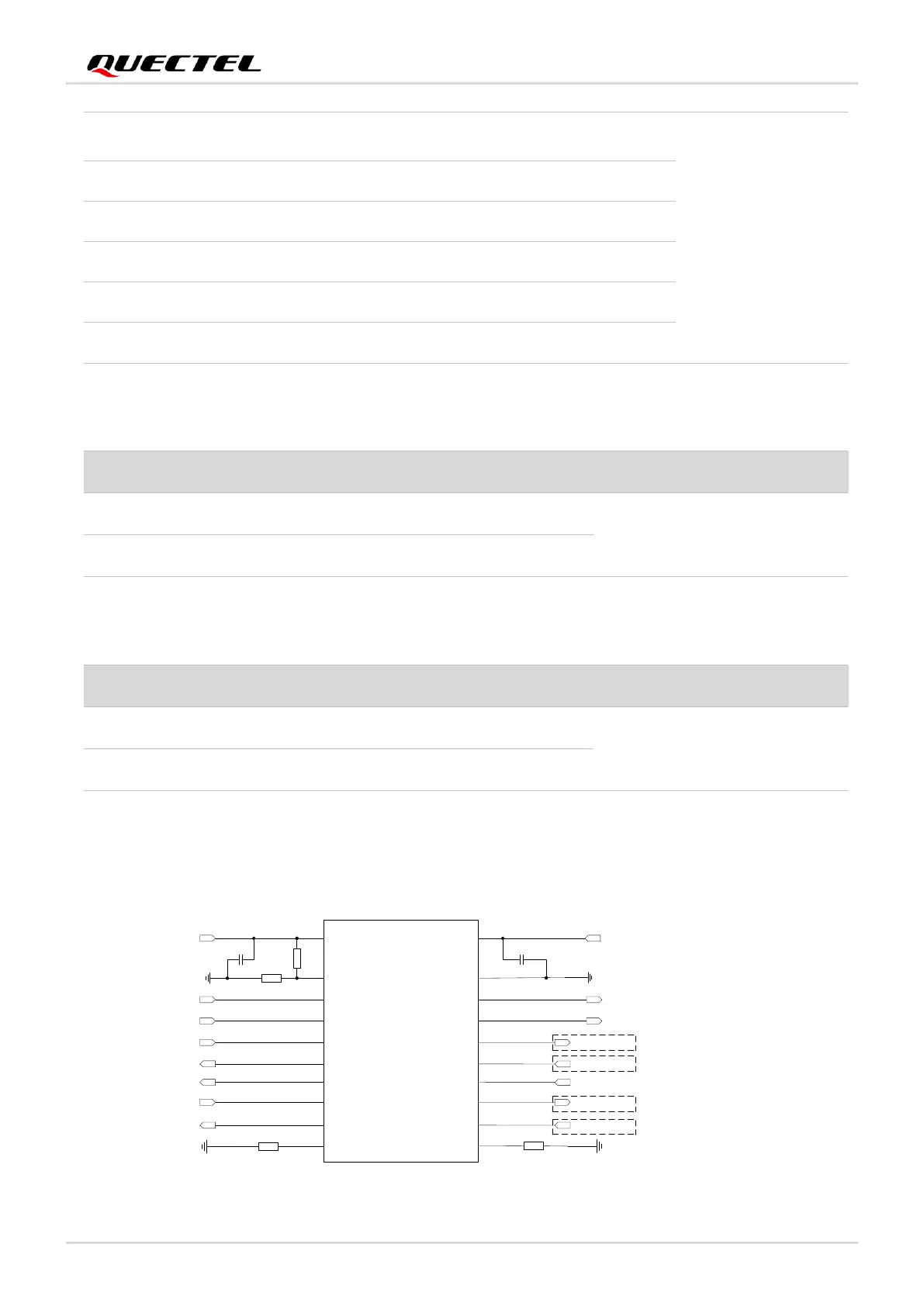
The module provides 1.8 V UART interfaces. Use a level shifter if the application is equipped with a 3.3 V
UART interface. A level shifter TXS0108EPWR provided by Texas Instruments is recommended. The
following figure shows a reference design.
VCCA VCCB
OE
A1
A2
A3
A4
A5
A6
A7
A8
GND
B1
B2
B3
B4
B5
B6
B7
B8
VDD_EXT
MAIN_RI
MAIN_DCD
MAIN_RTS
MAIN_RXD
MAIN_DTR
MAIN_CTS
MAIN_TXD
51K
51K
0.1 μF
0.1 μF
RI_MCU
DCD_MCU
RTS_MCU
TXD_MCU
DTR_MCU
CTS_MCU
RXD_MCU
VDD_MCU
Translator
10K
120K
Connect the MCU CTS pin
Connect the MCU RTS pin
Connect the MCU RXD pin
Connect the MCU TXD pin
MAIN_RTS
37
DI
DTE request to send signal to
DCE (connect to DTE’s RTS)
open.
MAIN_RXD
34
DI
Main UART receive
MAIN_DCD
38
DO
Main UART data carrier detect
MAIN_TXD
35
DO
Main UART transmit
MAIN_RI
39
DO
Main UART ring indication
MAIN_DTR
30
DI
Main UART data terminal ready
Pin Name
Pin No.
I/O
Description
Comment
DBG_RXD
22
DI
Debug UART receive
1.8 V power domain.
If unused, keep it open.
DBG_TXD
23
DO
Debug UART transmit
Pin Name
Pin No.
I/O
Description
Comment
AUX_TXD
27
DO
Auxiliary UART transmit
1.8 V power domain.
If unused, keep it open.
AUX_RXD
28
DI
Auxiliary UART receive

Table of Contents

Other manuals for Quectel EG915U Series

Questions and Answers:

Question and Answer IconNeed help?

Do you have a question about the Quectel EG915U Series and is the answer not in the manual?

Quectel EG915U Series Specifications

General IconGeneral
BrandQuectel
ModelEG915U Series
CategoryControl Unit
LanguageEnglish

Related product manuals