LTE Standard Module Series
EG915U_Series_Hardware_Design 42 / 81
layer and ground planes above and below.
⚫ Pay attention to the selection of the ESD component on the USB data line. Its stray capacitance
should not exceed 2 pF and should be placed as close as possible to the USB connector.
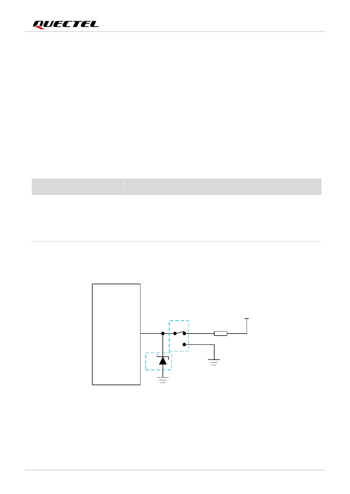
4.3. USB_BOOT Interface
The module provides a USB_BOOT pin. You can pull up USB_BOOT to VDD_EXT before power-up and
the module will enter download mode when it is turned on. In this mode, the module supports firmware
upgrade over USB interface.
Table 12: Pin Definition of USB_BOOT Interface
The following figure shows a reference circuit of USB_BOOT interface.

 Loading...


